Automatic occlusion detection in road network data

a technology of road network data and automatic occlusion detection, applied in the direction of image enhancement, instruments, and using reradiation, can solve the problems of lidar occlusion, false negative of pertinent roadside objects blocked by semi-trucks, and detriment to the performance of localization algorithms

Active Publication Date: 2020-02-04
HERE GLOBAL BV
View PDF9 Cites 6 Cited by
  • Summary
  • Abstract
  • Description
  • Claims
  • Application Information

AI Technical Summary

Problems solved by technology

Gaps in a 3D map, such as missing objects, structures and / or other localization objects, may be detrimental to the performance of localization algorithms.
Gaps in the 3D map often exist due to “false negatives” generated by object detection algorithms, frequently due to missing input data.
In this example, the LIDAR scanner only captures data of the semi-truck, resulting in a LIDAR occlusion and a false negative for the pertinent roadside objects blocked by the semi-truck.
In practice, there is typically traffic and other temporary objects randomly obscuring the view of data collection vehicle.
As a result of the large tanker truck 406 obscuring the view of the sensors of the data collection vehicle, a 3D vehicle localization map / model generated from the collected data will be incomplete.
Further, object detection algorithms may generate a false negative indicating that no roadside objects exist in the area obscured by tanker truck 406, resulting in a conclusion that is detrimental to the mapmaking process.
As such, cropping / clipping the sensor data to define a region of interest limits the locations where an algorithm may detect occlusions.
If the source of an occlusion is a permanent object, such as a wall, targeted remapping may be unsuccessful because the occlusion is likely to appear in the remapping.
The partial occlusion may not fully occlude the view of roadside object, but may lower the sampling rate by the data collection vehicle (e.g., no full gaps in sensor data, but a lower sampling rate cause by some rays hitting roadside objects and other rays hitting the small vehicle).
Additionally, the illustrations are merely representational and may not be drawn to scale.

Method used


Image

  • Automatic occlusion detection in road network data
  • Automatic occlusion detection in road network data
  • Automatic occlusion detection in road network data

Examples


embodiment 1

[0118

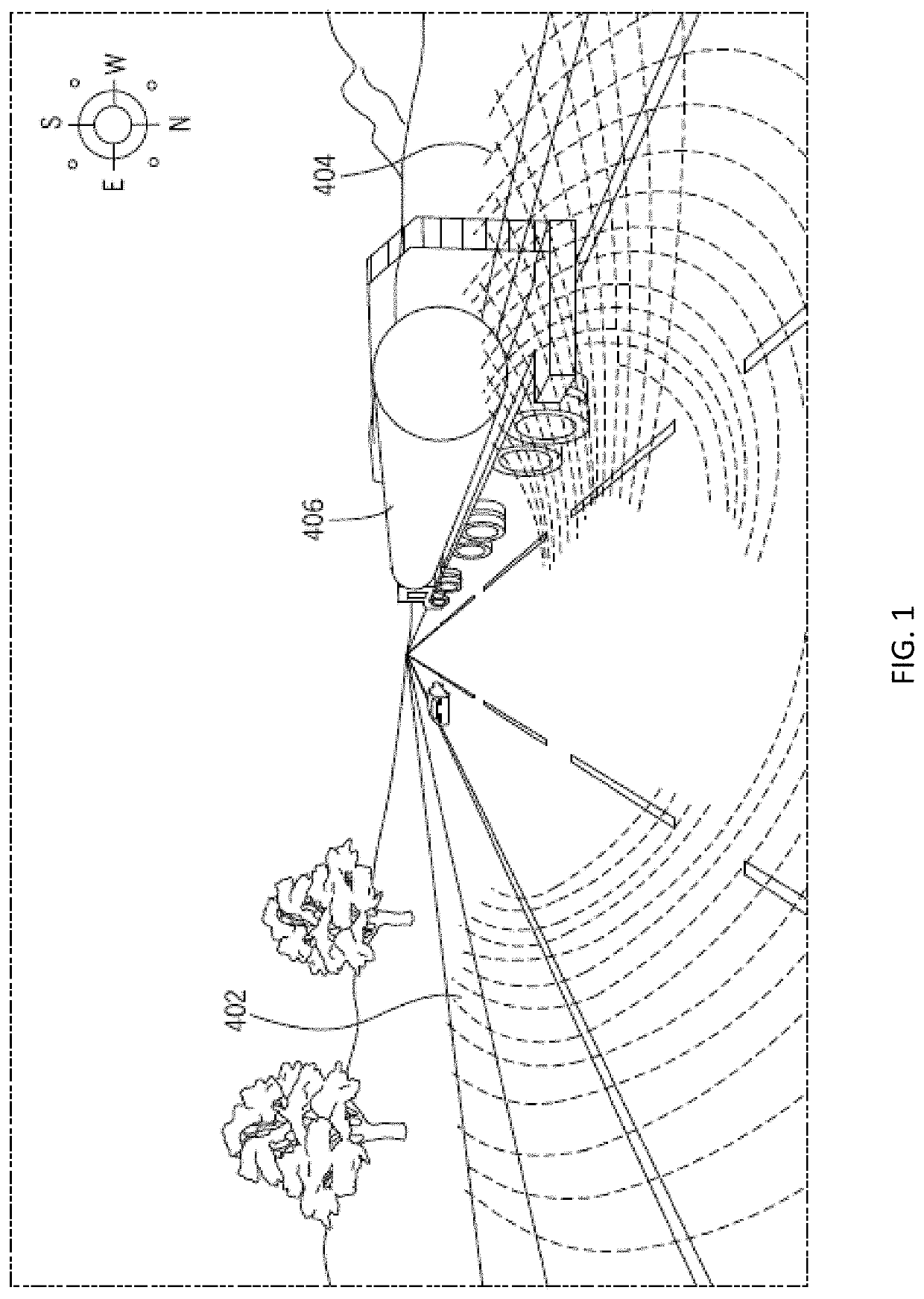
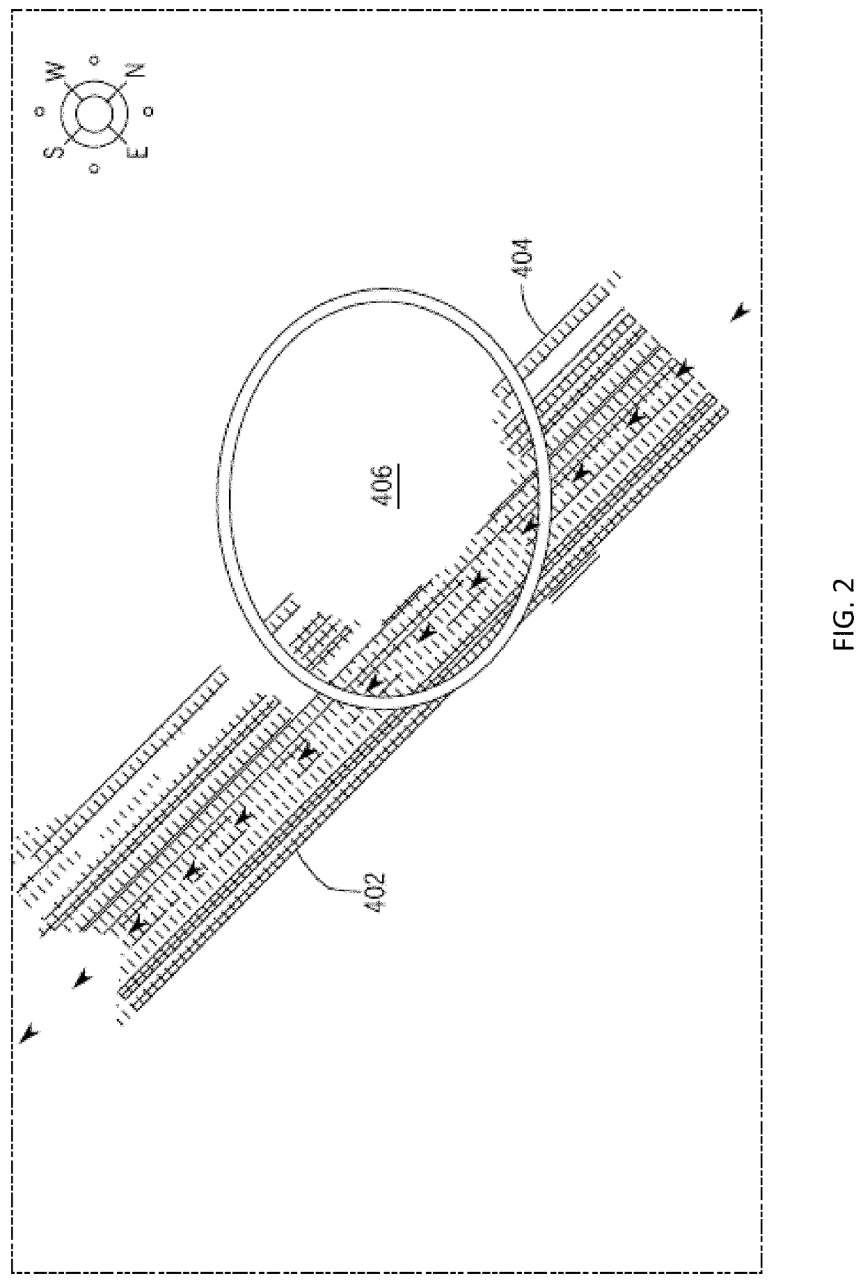
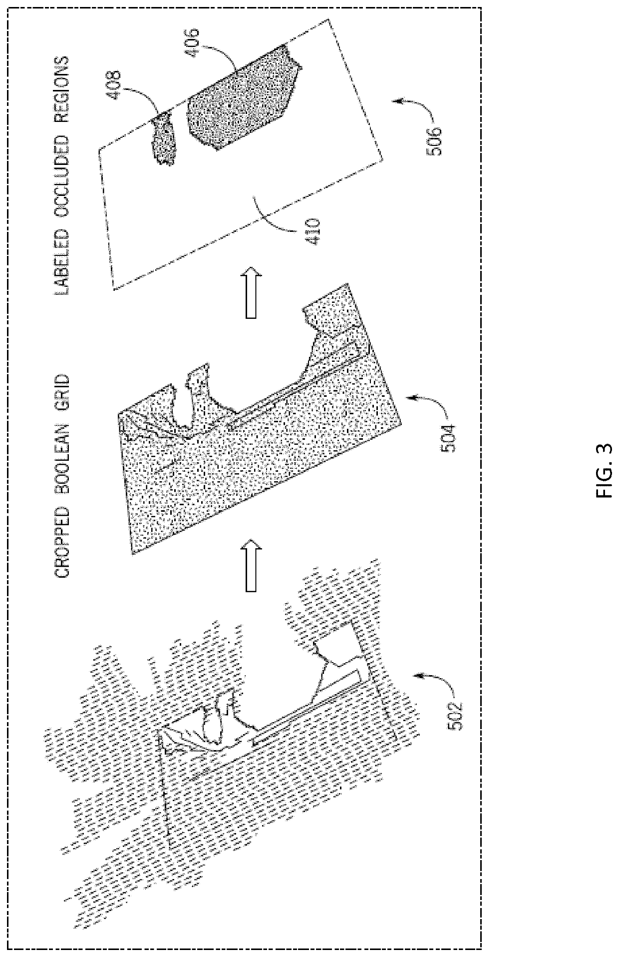
[0119]A method of detecting an occlusion from point cloud data, the method comprising:[0120]receiving, by a server from a data collection vehicle, point cloud data for a scene;[0121]generating, by the server from the point cloud data, a grid representation of a region of interest in the scene, wherein the grid representation comprises free space, occupied space and hidden space; and[0122]identifying, by the server, an occlusion in the region of interest based on the hidden space of the grid representation.

embodiment 2

[0123

[0124]The method according to embodiment 1, wherein the region of interest is defined based on a traffic lane model.

embodiment 3

[0125

[0126]The method of any of the preceding embodiments 1 to 2, wherein the free space corresponds to a location between a sensor location and a corresponding object location identified from the point cloud data, the occupied space corresponds to the object location identified from the point cloud data, and the hidden space corresponds to a location without point cloud data.


PUM


Abstract

The present embodiments provide for automatically detecting the location and severity of occluded regions within input data. A grid representation of a scene is generated from a data set, characterizing spaces of the grid representation as free, occupied, and hidden / occluded. The grid is bounded, and a connected component analysis is performed on the hidden space to identify the occluded regions.

Description

FIELD[0001]The following disclosure relates to three-dimensional (3D) occlusion detection, and more particularly to 3D map generation, navigation and autonomous driving.BACKGROUND[0002]Autonomous driving, augmented reality and navigation applications often rely on three-dimensional (3D) object detection based on a 3D map or model of a local scene. For example, to take advantage of high-definition 3D maps, autonomous vehicles sense the environment surrounding the vehicle and match the environment to the 3D map using a process called localization. The localization process relies on pertinent objects, structures and other localization objects in the vehicle environment to be present in the 3D map.[0003]Gaps in a 3D map, such as missing objects, structures and / or other localization objects, may be detrimental to the performance of localization algorithms. Gaps in the 3D map often exist due to “false negatives” generated by object detection algorithms, frequently due to missing input dat...

Claims


Application Information

Patent Timeline
Patent Type & Authority Patents(United States)
IPC IPC(8): G06K9/00G01S17/42G01S17/93G01S17/89G06T7/521G01S7/48G05D1/02G01S17/931
CPCG06T7/521G06K9/00798G01S17/89G06K9/00791G01S17/42G01S7/4808G06T2207/10028G01S17/931G05D1/0231G06T2207/30252G06V20/56G06V20/588
Inventor DORIA, DAVIDCHEN, XINPARKER, COBY SPOLINLI, ZICHEN
Owner HERE GLOBAL BV
Why Eureka
Try Eureka