Mechanical seal with high pressure high temperature secondary seal

a mechanical seal and high temperature technology, applied in the direction of engine seals, mechanical apparatus, engine components, etc., can solve the problems of not being able to permanently fix unable to achieve the effect of permanent fixing of the seal face to the shaft and housing, and using a secondary seal that includes a gasket and/or o-ring, etc., to achieve the effect of simple design, extended the operating temperature range of mechanical seals, and easy installation and removal

Active Publication Date: 2020-02-11
FLOWSERVE PTE LTD
View PDF17 Cites 0 Cited by
  • Summary
  • Abstract
  • Description
  • Claims
  • Application Information

AI Technical Summary

Benefits of technology

[0012]A high temperature, high pressure secondary seal design is disclosed that is simple in design (at least compared to a metallic bellows seal), easy to install and remove, extends the operating temperature range of a mechanical seal beyond existing limits, and, in embodiments, facilitates axial movement of an associated seal face. The novel secondary seal design includes an annular sealing gasket and a backing plate that surround an underlying cylindrical sealing surface, which can be the outer surface of the rotating shaft, or of a collar that surrounds the rotating shaft and is fixed to either the shaft or to the housing. In embodiments, all three of these elements are made of the same metallic material, so that effects of expansion and contraction with temperature are minimized. In embodiments, the metallic material is Alloy 718 or another “super alloy” that maintains its strength at high temperatures.
[0014]The sealing gasket is shaped as approximately one-half of a hollow ring, so that the cross section thereof is shaped approximately like a capital letter “C”. In embodiments, the sealing gasket is manufactured through a stamping process, whereby an initially flat, annular metal ring is pressed between two close tolerance forms to create the “C” cross-sectional shape. Accordingly, the sealing gasket is much simpler and less expensive to manufacture than a typical non-pusher, metallic bellows.
[0015]The curved portion of the C-shaped sealing gasket profile is directed toward a C-shaped groove provided in the backing plate, so that when axial pressure is applied, the gasket is pressed into the groove. However, the groove in the backing plate ends before it reaches the underlying sealing surface, so that the radially innermost portion of the gasket is exposed. This allows the inner radius of the C-shaped sealing gasket to deform under pressure and form an enhanced seal against the sealing surface.
[0019]As noted above, in embodiments, after assembly and before initial operation, the inner diameter of the sealing gasket forms an interference fit with the outer diameter of the cylindrical sealing surface at ambient pressure and temperature. During operation, as the applied pressure and temperature of the process fluid increases, the sealing gasket is pressurized against the groove provided in the backing ring, causing it to yield and conform to the exact shape of the groove. At the same time, the exposed inner diameter of the gasket is pressed downward, so that it deforms against the outer diameter of the cylindrical sealing surface and the region of contact transitions from a line of contact to a surface of contact. As the pressure continue to increase, the area of the contact surface increases, improving the quality of the seal that prevents the pressurized fluid from passing between the inner diameter of the gasket and the outer diameter of the cylindrical surface.
[0021]When operation ceases and the operating fluid pressure is relieved, the deformed inner diameter of the gasket naturally retracts away from the underlying sealing surface, thereby creating a clearance fit to the cylindrical sealing surface, and allowing the sealing gasket, backing plate, and associated seal face to be easily removed and reinstalled during disassembly and maintenance. In embodiments, the clearance of the clearance fit is between 0.0005 and 0.001 inches. Nevertheless, upon re-pressurizing during subsequent operation, the seal is improved and the leakage past the gasket, if any, is reduced in comparison to the initial operation.
[0022]In embodiments, the sealing gasket is manufactured via a stamping process, wherein a flat sheet-metal ring is pressed between two close-tolerance forms. This allows the mechanical seal faces to maintain the appropriate gap required for operation at all times. Additionally, in embodiments the sealing gasket, backing plate, and sealing surface are all composed of identical materials, so that thermal expansion is uniform throughout the secondary seal, thereby preventing any one of the components from unintentionally expanding or contracting away from or into one of the others. As a result, all established clearances and interferences are maintained regardless of temperature variations.

Problems solved by technology

Generally, this is such a small amount that if the leaked fluid is a liquid, it tends to evaporate rather than pool, and therefore remains unnoticed.
Generally, it is not practical to permanently fix the seal faces to the shaft and housing.
For this reason, the use of a secondary seal that includes a gasket and / or O-ring can limit the maximum temperature at which a mechanical seal can operate, due to temperature limitations of the elastomer.
Non-pusher secondary seals that use a metal bellows can withstand higher operating temperatures as compared to elastomer secondary seals, but metallic bellows seals are complex, expensive, difficult to install and remove, subject to metal fatigue, and are still sometimes not able to withstand the full range of temperatures that may be desirable for a given application.

Method used


Image

  • Mechanical seal with high pressure high temperature secondary seal
  • Mechanical seal with high pressure high temperature secondary seal
  • Mechanical seal with high pressure high temperature secondary seal

Examples


Embodiment Construction

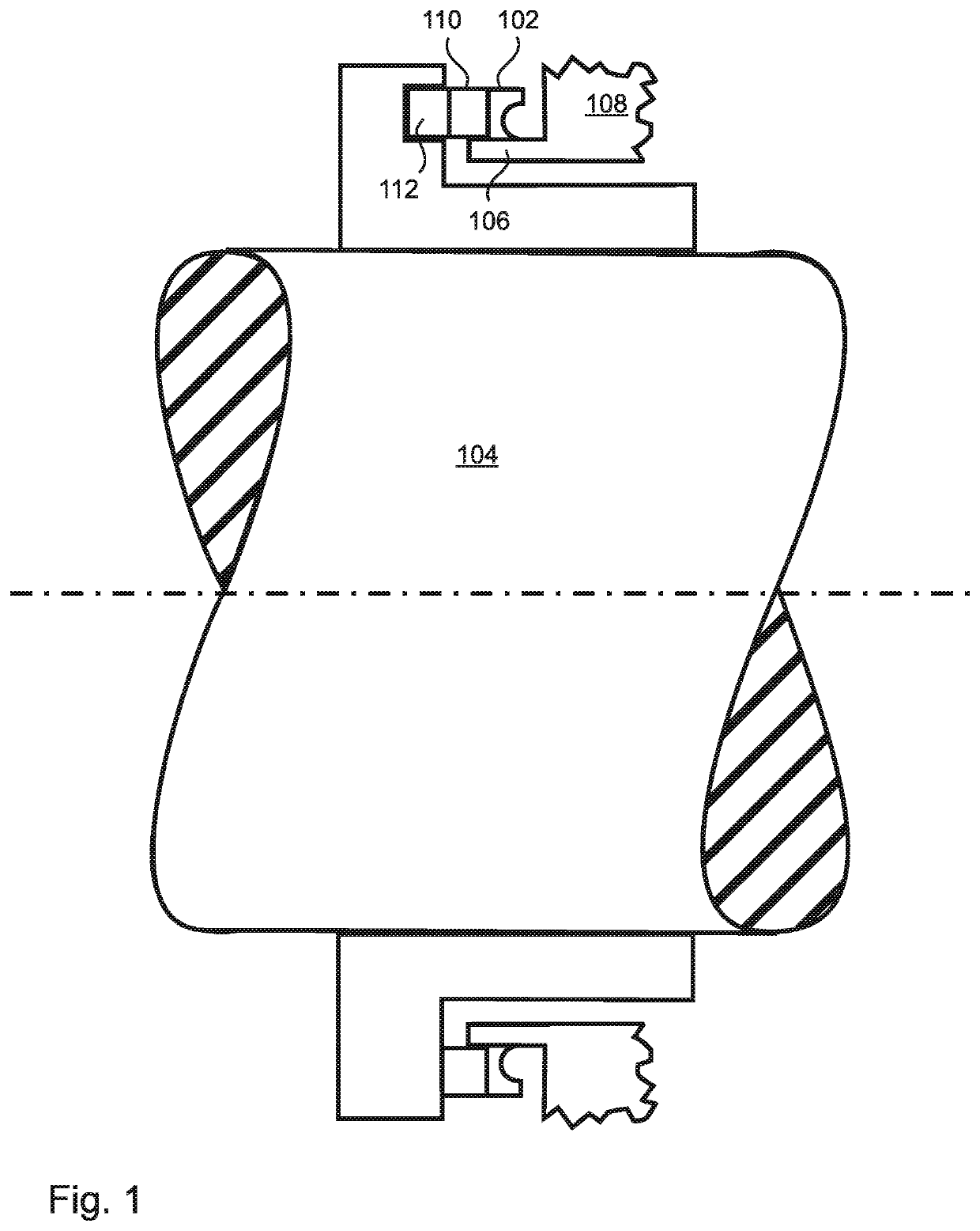
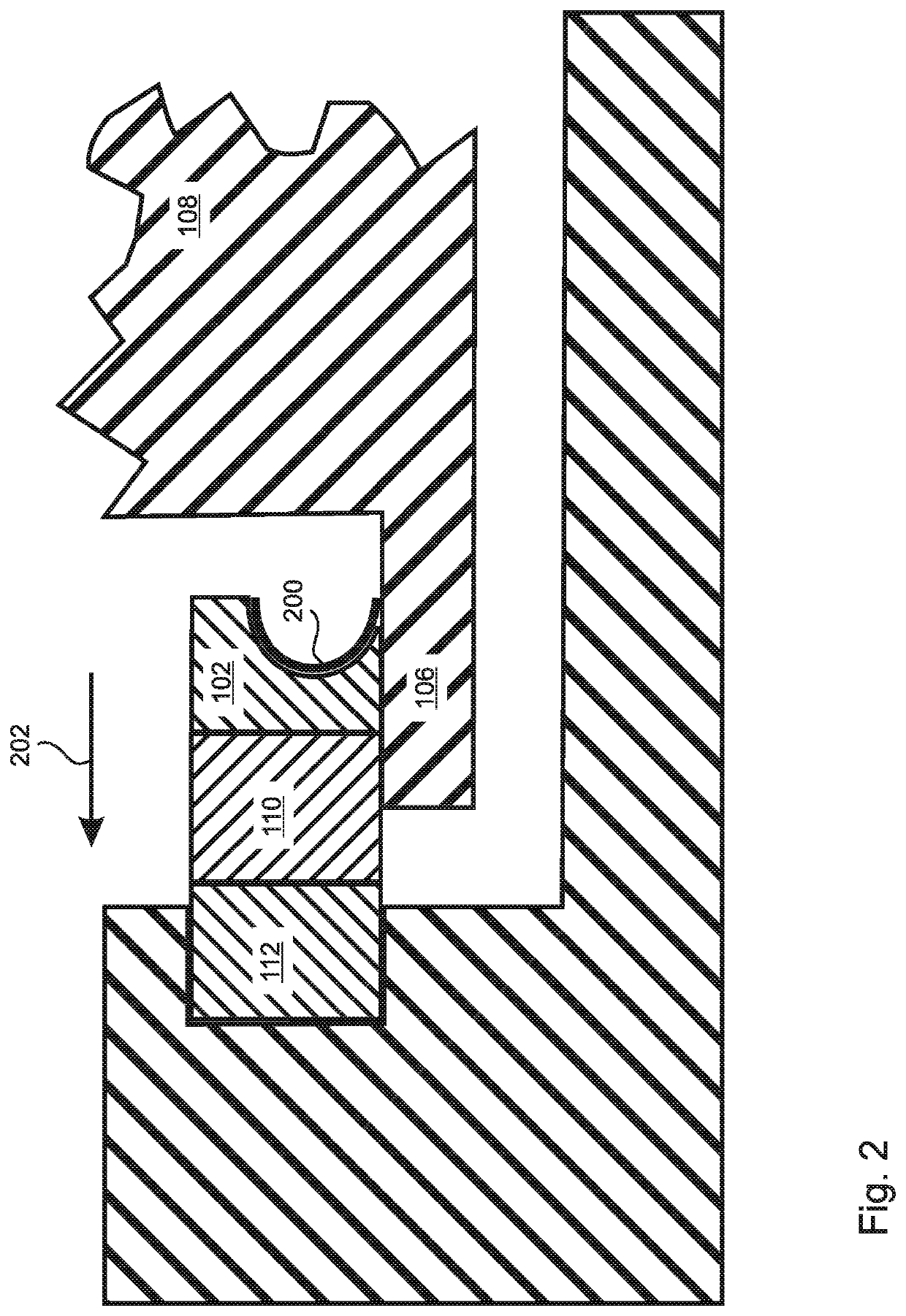
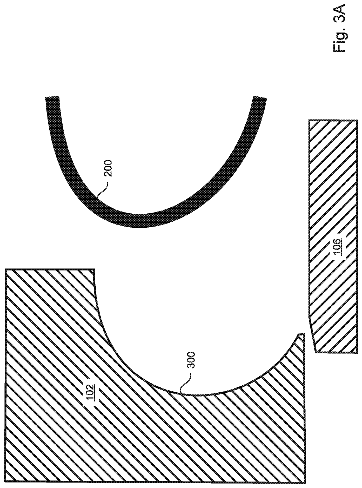
[0045]The present invention is a high temperature, high pressure static seal design that extends the operating temperature range of a mechanical seal beyond existing limits, and which preferably facilitates axial movement of an associated seal face. With reference to FIGS. 1 and 2, the novel seal design includes an annular sealing gasket 200 and a backing plate 102 that surround an underlying cylindrical sealing surface, which can be the outer surface of the rotating shaft 104 or of a collar 106 that surrounds the rotating shaft and is fixed to either the shaft 104 or to the housing 108. In the embodiment of FIGS. 1 and 2, the sealing surface is a collar 106 that surrounds the shaft 104, but is static and fixed to the housing 108. The backing plate 102 is sealed to an associated seal face 110, which in FIGS. 1 and 2 is the static seal face 110, which forms a seal with the other seal face 112, which in FIGS. 1 and 2 is the rotating seal face 112. Although no specific mechanism is sho...


PUM

PropertyMeasurementUnit
diameteraaaaaaaaaa
diameteraaaaaaaaaa
thicknessaaaaaaaaaa

Abstract

A secondary seal of a mechanical seal comprises an annular sealing gasket and backing plate surrounding a cylindrical sealing surface, all of which can be made of the same metallic material. The gasket is C-shaped in cross section, and is axially pressed during operation into a C-shaped groove formed in the backing plate, the groove being shallower and larger in inner diameter than the gasket, so that the gasket, when pressed into the groove, deforms radially inward and seals against both the backing plate and the sealing surface. The contact area between the gasket and sealing surface increases with pressure. In embodiments, when the pressure is released, the gasket retracts from the sealing surface, allowing easy disassembly and allowing axial movement of the gasket and backing plate. Highly polished surfaces of the gasket and sealing surface can allow axial motion thereof during operation to maintain the seal face gap.

Description

STATEMENT OF GOVERNMENT INTEREST[0001]This invention was made under CRADA 1872.00.00 between Flowserve and Sandia National Labs operated for the United States Department of Energy. The Government may have certain rights in this invention.FIELD OF THE INVENTION[0002]The invention relates to rotating shaft seals, and more particularly, to rotating shaft mechanical seals.BACKGROUND OF THE INVENTION[0003]A mechanical seal is a seal that is formed by close proximity of two flat, annular, non-contacting seal faces, usually referred to as a static seal face and a rotating seal face, in that one face is typically static and sealed to a housing, while the other face is sealed to a rotating shaft and rotates with the shaft. The two seal faces are annular, and coaxial with the rotating shaft, whereby the long axis of the shaft is also the common axis of the annular seal faces.[0004]Traditionally the two seal faces are lapped flat to a very high degree of flatness, which allows the faces to be ...

Claims


Application Information

Patent Timeline
Patent Type & Authority Patents(United States)
IPC IPC(8): F16J15/38F16J15/36F16J15/34
CPCF16J15/38F16J15/3464F16J15/363F16J15/344F16J15/3452F16J15/3472F16J15/3448F16J15/3228
Inventor HAMILTON, ERICNELSON, DANIEL
Owner FLOWSERVE PTE LTD
Why Eureka
Try Eureka