Reduction of power peaks in the spectrum of the mean power of fill level measuring devices

a technology of fill level and power peaks, which is applied in the field of level measurement, can solve the problem that the peak power of the transmission signal cannot be influenced by, and achieve the effect of reducing power peaks and level increases and improving power spectrum

Active Publication Date: 2020-02-11
VEGA GRIESHABER GMBH & CO
View PDF18 Cites 0 Cited by
  • Summary
  • Abstract
  • Description
  • Claims
  • Application Information

AI Technical Summary

Benefits of technology

[0006]There is a desire to provide a method for reducing power peaks and level increases in the spectrum of the mean power of fill level measuring devices, as well as a fill level measuring device having an improved power spectrum with regard to the permitted maximum transmission level.
[0012]The distinction between a fundamental frequency interval and a frequency range between the minimal frequency fmin and the maximal frequency fmax of a frequency ramp of a transmission signal has the following effect: a fill level measuring device operating with a frequency-modulated continuous wave signal has circuit parts that can have a certain settling or warm-up time. Transmission signals that are emitted during the period of the settling or warm-up time of these circuit parts cannot be used for a reliable measurement, i.e. for reliable determination of the level. A component of a transmission signal used for measurement can advantageously be given by a frequency ramp, i.e. signal components in which a transmission signal component having a constant frequency is emitted over a certain period can be undesirable when taking a measurement. On account of necessary settling or warm-up times, it might not be sensible to start directly with a frequency ramp. For this reason, it is possible to initially wait until after the settling or warm-up time at a constant frequency before the following part of the transmission signal is given by a frequency ramp. The present invention avoids the emission of a transmission signal component of constant frequency during the settling or warm-up period in that part the frequency ramp is already passed through during this period but is not used for the actual measurement. In this way, times in which a transmission signal component of constant frequency is emitted can be eliminated completely or at least significantly reduced.
[0026]Using this method, resting of a component of the transmission signal during the settling or warm-up time of circuit parts of the fill level measuring device can be avoided or at least significantly reduced. For example, the period in which a component of the transmission signal having a constant frequency is radiated is reduced by a factor of 4 compared with the settling or warm-up time. Reduction by a factor of 10 is also possible. Furthermore, a period during which a frequency-constant transmission signal is emitted can also be eliminated completely. In the aforementioned cases, the transmission signal can already pass through part of a frequency ramp during the settling or warm-up time. On expiry of the settling time, a minimal or, in the case of a falling frequency ramp, a maximal frequency of the fundamental frequency interval is then attained along the frequency ramp. The transmission signal components for determining the level are used after this frequency.

Problems solved by technology

However, the peak power of the transmission signal cannot be influenced by this.

Method used


Image

  • Reduction of power peaks in the spectrum of the mean power of fill level measuring devices
  • Reduction of power peaks in the spectrum of the mean power of fill level measuring devices
  • Reduction of power peaks in the spectrum of the mean power of fill level measuring devices

Examples


Embodiment Construction

[0038]Embodiments of the invention are illustrated below with reference to the figures. Features and properties that are described in connection with a fill level measuring device can likewise be transferred to the method in this case, as, vice versa, steps of the method can be implemented in the fill level measuring device and its operation.

[0039]The representation in the figures is schematic and not to scale. Where the same reference signs are used in different figures, these denote the same or similar elements.

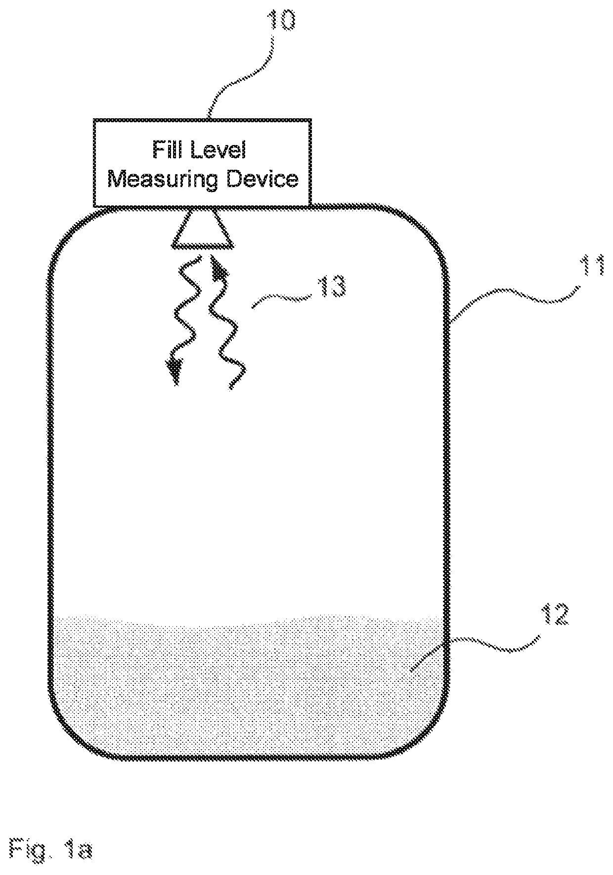
[0040]FIG. 1a shows a fill level measuring device 10, which is attached to an upper vessel wall of a vessel or container 11 or is inserted at least in part into the interior of the vessel through an opening in the upper vessel wall. Located inside the vessel 11 is a filling material 12. To determine the level of the filling material 12 inside the vessel 11, the fill level measuring device 10 can emit transmission signals 13 towards the filling material, which are reflected ...


PUM


Abstract

A fill level measuring device designed for the generation and emission of a transmission signal, wherein the transmission signal includes at least one frequency ramp. In order to determine the level of a filling material in a vessel, only frequencies within a fundamental frequency interval are used. In this case, the minimal frequency of the fundamental frequency interval is greater than the minimal frequency of the frequency ramp and / or the maximal frequency of the fundamental frequency interval is smaller than the maximal frequency of the frequency ramp. The approach provides a reduction of power peaks in the frequency spectrum of the mean power of fill level measuring devices, which peaks result from times in which the fill level measuring device emits a constant frequency before the beginning of or after a frequency ramp.

Description

REFERENCE TO RELATED APPLICATIONS[0001]This application claims the benefit of the filing date of European Patent Application No. 16 156 684.9 filed on 22 Feb. 2016, the disclosure of which is hereby incorporated herein by reference.FIELD OF THE INVENTION[0002]The invention relates to level measurement. In particular, the invention relates to a method for reducing power peaks in the frequency spectrum of the mean power of the transmission signal of fill level measuring devices, to a level radar, to a program element and to a computer-readable medium.BACKGROUND[0003]When determining the level of a filling material in a vessel or outside of closed vessels (free field), fill level measuring devices can be used, which emit radar or ultrasonic signals towards the filling material and register the signal reflected at the filling material, in order to ascertain a level therefrom.[0004]In the spectra of the power averaged over time of fill level measuring devices (also termed RMS spectrum (R...

Claims


Application Information

Patent Timeline
Patent Type & Authority Patents(United States)
IPC IPC(8): G01F23/284G01S7/35G01S13/00
CPCG01S7/35G01F23/284G01R21/00G01S13/88G01S13/343
Inventor MUELLER, CHRISTOPHFISCHER, MICHAEL
Owner VEGA GRIESHABER GMBH & CO
Why Eureka
Try Eureka