
Server apparatus, method of controlling the server apparatus, storage medium, and printing system that determine whether to perform, in the server apparatus, rendering processing on a page of a print job

a server and server technology, applied in the direction of digital output to print units, instruments, computing, etc., can solve the problems of long time, transmission of data, and inability to perform so as to prevent the rendering of print jobs, shorten the execution time, and shorten the time

Active Publication Date: 2020-02-11
CANON KK
View PDF6 Cites 1 Cited by
  • Summary
  • Abstract
  • Description
  • Claims
  • Application Information

AI Technical Summary

Benefits of technology

This approach shortens the time users wait for print processing to complete by optimizing rendering processing according to the printing apparatus's capabilities, minimizing unnecessary load on the print server and reducing overall system load.

Problems solved by technology

In a case in which, when processing for rendering a print job received from the print server takes a long time on the printing apparatus, however, the user may be made to wait in front of the printing apparatus until the print processing completes.
In the foregoing conventional technique, however, processing for rendering the print job is not performed until a print instruction is made by the user on the printing apparatus.
It takes a long time, however, to transmit data in the case of transmitting the print job to the printing apparatus after the rendering processing by the print server, since the data amount of the image data to be transmitted will be larger.
Meanwhile, in the case of performing processing for rendering the entire print job on the printing apparatus, there is the possibility that the rendering processing will take a long time depending on the print job.

Method used


Image

  • Server apparatus, method of controlling the server apparatus, storage medium, and printing system that determine whether to perform, in the server apparatus, rendering processing on a page of a print job
  • Server apparatus, method of controlling the server apparatus, storage medium, and printing system that determine whether to perform, in the server apparatus, rendering processing on a page of a print job
  • Server apparatus, method of controlling the server apparatus, storage medium, and printing system that determine whether to perform, in the server apparatus, rendering processing on a page of a print job

Examples


Embodiment Construction

[0030]Hereafter, embodiments of the present invention will be described in detail with reference to the accompanying drawings. It should be noted that the following embodiments are not intended to limit the scope of the appended claims, and that not all the combinations of features described in the embodiments are necessarily essential to the solving means of the present invention.

[0031]Printing System

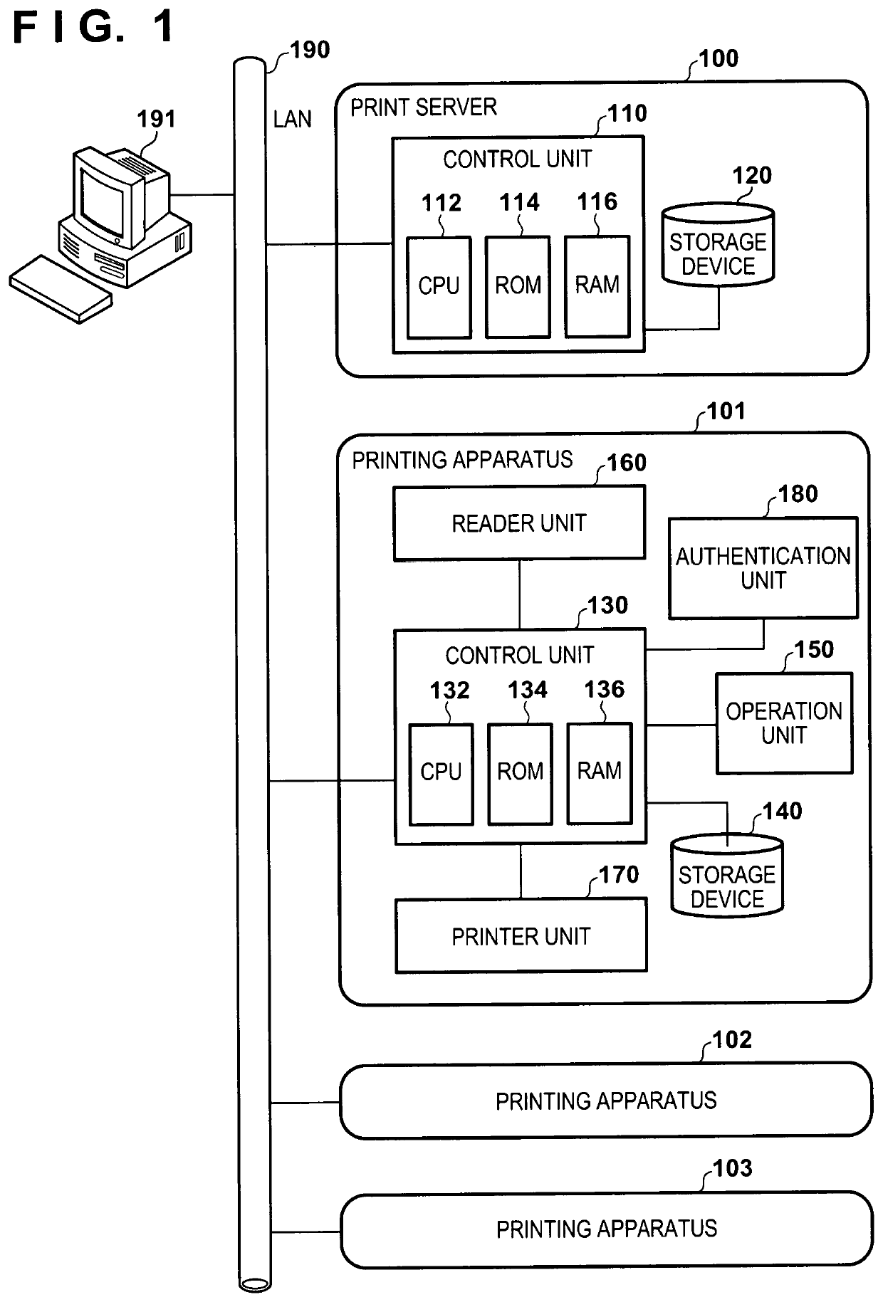
[0032]FIG. 1 is a block diagram that illustrates an example of a configuration of a printing system according to embodiments of the present invention. A print server 100, a plurality of printing apparatuses (image forming apparatuses) 100 to 103, and a personal computer (PC) 191 are connected so as to be able to communicate with each other via a local area network (LAN) 190 in the printing system that is illustrated in FIG. 1. Note, the PC 191 can be configured by a general-purpose computer.

[0033]Although the printing apparatuses 101 to 103 are multi function printers (MFPs) in the pre...


PUM


Abstract

A server apparatus includes a controller that determines, for a page of a held print job, whether or not to perform rendering processing in the server apparatus, performs, in accordance with a result of the determination, the rendering processing on a page determined to be a target page of the rendering processing in the print job, and transmits, to a printing apparatus, a print job including data of the page for which the rendering processing is performed. A processing time allowed for print processing per page is determined based on capability information indicating a capability of the printing apparatus that is to execute the print job, and the target page is determined based on the determined processing time.

Description

[0001]This application claims the benefit of Japanese Patent Application No. 2017-163668, filed Aug. 28, 2017, which is hereby incorporated by reference herein in its entirety.BACKGROUND OF THE INVENTIONField of the Invention[0002]The present invention relates to a server apparatus, a method of controlling the same, a storage medium, and a printing system, and, in particular, relates to a technique for shortening the time required for rendering processing that a printing apparatus performs on a print job transmitted from a server apparatus.Description of the Related Art[0003]In recent years, as a configuration in which multiple users share multiple image forming apparatuses (printing apparatuses), a printing system in which a user, rather than designating a printing apparatus uniquely from an information processing apparatus, such as a personal computer (PC), causes a desired printing apparatus to execute printing (referred to as “remote printing”) is known. In remote printing, a us...

Claims


Application Information

Patent Timeline
Patent Type & Authority Patents(United States)
IPC IPC(8): G06F3/12
CPCG06F3/1259G06F3/1261G06F3/1215G06F3/1204G06F3/1288G06F3/1286G06F3/1273G06F3/1212G06F3/1247G06F3/126
Inventor SAKURAI, MASAKATSU
Owner CANON KK
Learn More