Casing for a rotating machine and rotating machine including such casing

a technology for rotating machines and casings, which is applied in the direction of machines/engines, mechanical equipment, liquid fuel engines, etc., can solve the problems of not allowing the protection of split flange bolts, no means to detect gas leaks inside the machine, and no preemptive action is possible to avoid risk for people or machines, etc., to achieve efficient monitoring and control of leaks

Active Publication Date: 2020-02-18
NUOVO PIGNONE TECH SRL
View PDF35 Cites 0 Cited by
  • Summary
  • Abstract
  • Description
  • Claims
  • Application Information

AI Technical Summary

Benefits of technology

[0002]In the above field, it is known to build casings including two half shells joined together along respective split flanges, where sealing is granted by the pulling force applied on the flanges by a plurality of bolts. In some applications an area around the bolt holes is machined to reduce the contact area, thus improving the sealing.
[0005]It would be therefore desirable to provide an improved casing which could avoid the inconveniences above described.
[0007]The presence of the separation groove around the bolt holes and of another groove, i.e. the control groove, between the separation groove and the internal casing diameter permits to efficiently monitoring and controlling leaks of process gas from the inner volume of the machine.

Problems solved by technology

Typically, no means to detect a gas leak from the split flange are present inside the machine.
Existing solutions to prevent external gas leaks, e.g. that described in U.S. Pat. No. 8,118,551, involve additional components or operations during production and do not allow the protection of the split flange bolts from process gas exposure.
Disadvantages of the existing solutions, in particular of that described in U.S. Pat. No. 8,118,551, are: no preemptive action is possible to avoid risk for people or machines.
Only an emergency reaction can be adopted in case of leak, especially when hazardous or aggressive gases are processed; in case of leak of process gas, no control of the leak source is possible and a shutdown of the machine is normally required for inspection and for defining possible corrective actions; known solutions are either outside AP1617 or involve additional components or operations during production and maintenance with increased cost and complexity; no embedded control system can be applied to passively or actively control the sealing performance and an eventual leak

Method used


Image

  • Casing for a rotating machine and rotating machine including such casing
  • Casing for a rotating machine and rotating machine including such casing
  • Casing for a rotating machine and rotating machine including such casing

Examples


Embodiment Construction

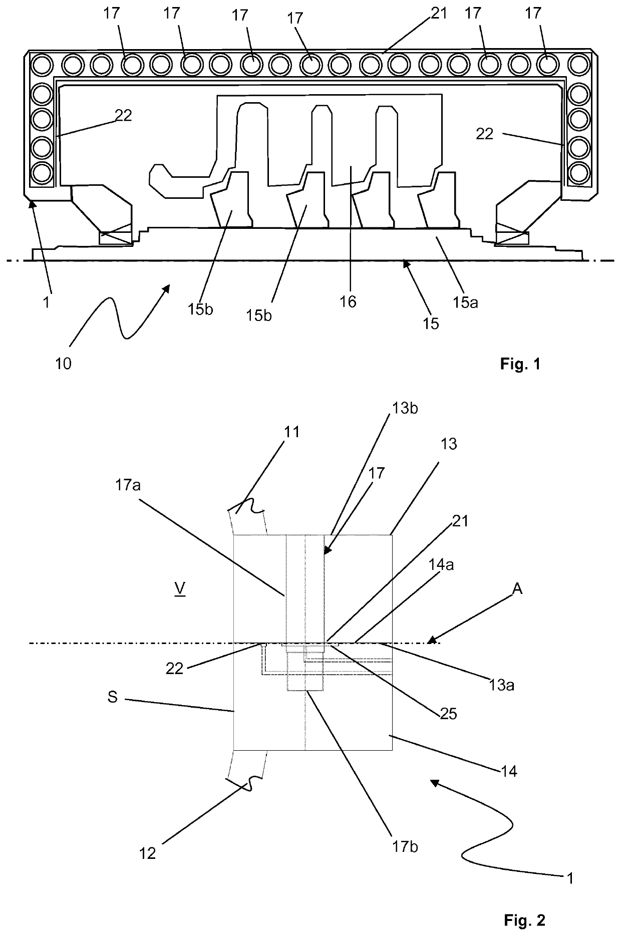
[0014]With reference to the attached Figures, a casing 1 for a rotating machine 10, for example a steam turbine (not represented) or a gas compressor (FIG. 1), includes an inner surface S delimiting an inner volume V for housing a rotor of the rotating machine 10. The casing 1 includes a first upper shell 11 and a second lower shell 12 that are joined together in a dividable manner in order to constitute the inner volume V. The first and second shells 11, 12 respectively comprise a first and a second split flange 13, 14 which respectively comprise a first and second split surface 13a, 14a. The first and second split surfaces 13a, 14a contact each other along a split plane A when the shells 11, 12 are joined together to form the casing 1, thus constituting the inner volume V for housing the rotor of the rotating machine 10.

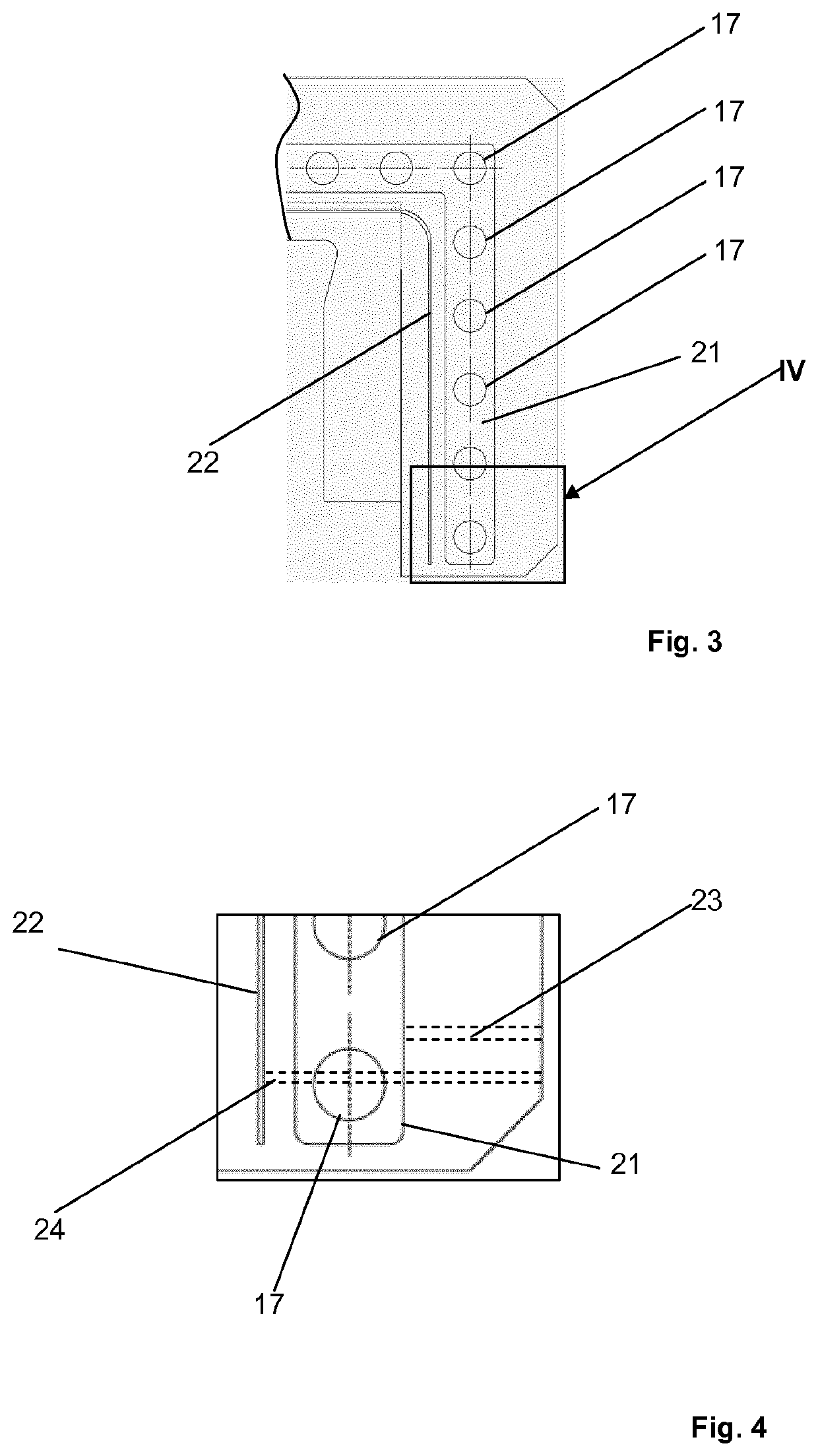
[0015]The casing 1 comprises a plurality of blind holes 17 on the first and second split flanges 13, 14 for joining the first and second shells 11, 12. The blind h...


PUM


Abstract

A casing for a rotating machine includes an inner surface delimiting an inner volume for housing a rotor of the rotating machine; a first and a second shell that are joined together in a dividable manner, the first and second shell respectively comprising a first and a second split flange having a first and a second split surface contacting each other when the shells are joined together; a plurality of holes on the first and second split flange passing through the first and second split surface for housing a plurality of bolts; a first groove connecting the plurality of holes; a second groove between the first groove and the inner surface of the casing; a first duct and a second duct for circulating a fluid to and from the first and second grooves, respectively.

Description

BACKGROUND[0001]Embodiments of the present invention relate to a casing for a rotating machine, for example a turbomachine such as steam turbine or a gas compressor, including sealing devices for controlling the sealing performance of the casing. Embodiments of the present invention also relate to a rotating machine including such casing.BRIEF DESCRIPTION OF THE INVENTION[0002]In the above field, it is known to build casings including two half shells joined together along respective split flanges, where sealing is granted by the pulling force applied on the flanges by a plurality of bolts. In some applications an area around the bolt holes is machined to reduce the contact area, thus improving the sealing.[0003]Typically, no means to detect a gas leak from the split flange are present inside the machine. Existing solutions to prevent external gas leaks, e.g. that described in U.S. Pat. No. 8,118,551, involve additional components or operations during production and do not allow the ...

Claims


Application Information

Patent Timeline
Patent Type & Authority Patents(United States)
IPC IPC(8): F01D25/24F04D27/00F04D29/08F01D11/00F04D29/52
CPCF04D29/522F04D29/083F04D27/001F01D25/243F01D11/005F05D2260/31F05D2220/30F16J15/14F16B5/02F01D25/24
Inventor ROMANELLO, PAOLOMANTELLASSI, STEFANOGUGLIELMO, ALBERTOSASSANELLI, GIUSEPPE
Owner NUOVO PIGNONE TECH SRL
Why Eureka
Try Eureka