Aluminum prop shaft with constant velocity joint

a technology of constant velocity and prop shaft, which is applied in the field of vehicles, can solve the problems of difficult joining of dissimilar metals, such as aluminum and steel, and achieve the effects of reducing or eliminating second-order energy noise and vibration, reducing manufacturing complexity, and reducing the additional mass

Active Publication Date: 2020-02-18
GM GLOBAL TECH OPERATIONS LLC
View PDF29 Cites 0 Cited by
  • Summary
  • Abstract
  • Description
  • Claims
  • Application Information

AI Technical Summary

Benefits of technology

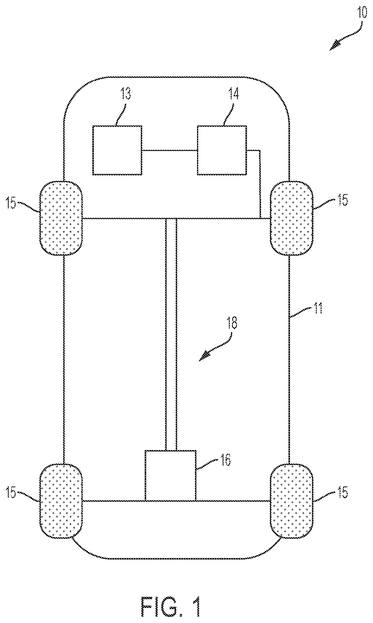
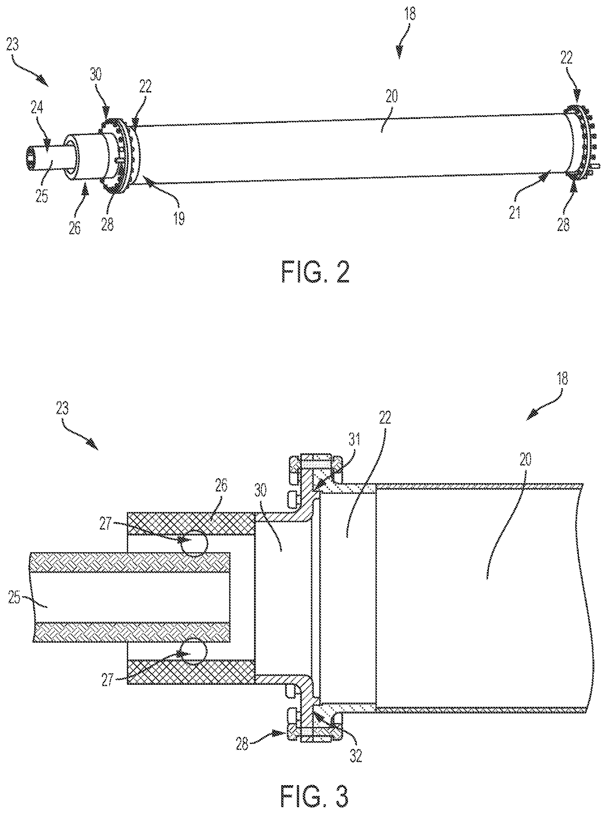
[0003]Embodiments according to the present disclosure provide a number of advantages. For example, embodiments according to the present disclosure enable a lightweight aluminum prop shaft tubing to be joined with a constant velocity (CV) joint to reduce or eliminate second order energy noise and vibration. Additionally, direct coupling of the aluminum prop shaft to the CV joint reduces the additional mass of an intervening component, such as a stub shaft, while also reducing manufacturing complexity. Embodiments according to the present disclosure optimize the use of large diameter, lightweight components to connect the CV joint to the main body of the prop shaft.

Problems solved by technology

However, joining dissimilar metals, such as aluminum and steel, is difficult and often requires an intervening member to join the dissimilar metal components.

Method used


Image

  • Aluminum prop shaft with constant velocity joint
  • Aluminum prop shaft with constant velocity joint

Examples


Embodiment Construction

[0021]Embodiments of the present disclosure are described herein. It is to be understood, however, that the disclosed embodiments are merely examples and other embodiments can take various and alternative forms. The figures are not necessarily to scale; some features could be exaggerated or minimized to show details of particular components. Therefore, specific structural and functional details disclosed herein are not to be interpreted as limiting, but merely as a representative basis for teaching one skilled in the art to variously employ the present invention. As those of ordinary skill in the art will understand, various features illustrated and described with reference to any one of the figures can be combined with features illustrated in one or more other figures to produce embodiments that are not explicitly illustrated or described. The combinations of features illustrated provide representative embodiments for typical applications. Various combinations and modifications of ...


PUM


Abstract

A prop shaft assembly for an automotive vehicle includes a main body having a first end and a second end, the first end coupled to a first flange and a constant velocity (CV) joint assembly including a first member and a second member, the second member coupled to a second flange. The first flange and the main body are made from aluminum, the second member and the second flange are made from steel, and the first flange and the second flange are coupled together by a plurality of mechanical fasteners.

Description

INTRODUCTION[0001]The present invention relates generally to the field of vehicles and, more specifically, to an aluminum prop shaft coupled with a constant velocity joint.[0002]Most vehicles include a powertrain assembly having an engine, a transmission, a driveline assembly, and driven wheels. A typical driveline assembly provides a power transfer path between an output shaft of the vehicle transmission and the driving axle assembly. Propeller shafts, drive shafts, or prop shafts which transmit power from an engine system to the wheel of an automotive vehicle are frequently constructed from one or more metal tubes connected with joints. However, joining dissimilar metals, such as aluminum and steel, is difficult and often requires an intervening member to join the dissimilar metal components.SUMMARY[0003]Embodiments according to the present disclosure provide a number of advantages. For example, embodiments according to the present disclosure enable a lightweight aluminum prop sha...

Claims


Application Information

Patent Timeline
Patent Type & Authority Patents(United States)
IPC IPC(8): F16D1/033B60K17/24B60K17/22F16D3/16
CPCF16D3/16B60K17/22F16D1/033B60K17/24F16D1/076F16D3/223F16D2003/22326
Inventor RODRIGUEZ, ROLANDO V.
Owner GM GLOBAL TECH OPERATIONS LLC
Why Eureka
Try Eureka