
Clutch assembly for automated manual transmission

a technology of automatic manual transmission and clutch, which is applied in the direction of clutches, gearing control, gearing elements, etc., can solve the problems of reducing the maneuverability of amts, reducing the capability to creep for extended durations, and reducing the low speed maneuverability of amts, so as to reduce the vibration, eliminate or reduce the effect of gear rattle and noise, and reduce the effect of nvh

Pending Publication Date: 2022-08-11
CUMMINS INC
View PDF0 Cites 0 Cited by
  • Summary
  • Abstract
  • Description
  • Claims
  • Application Information

AI Technical Summary

Benefits of technology

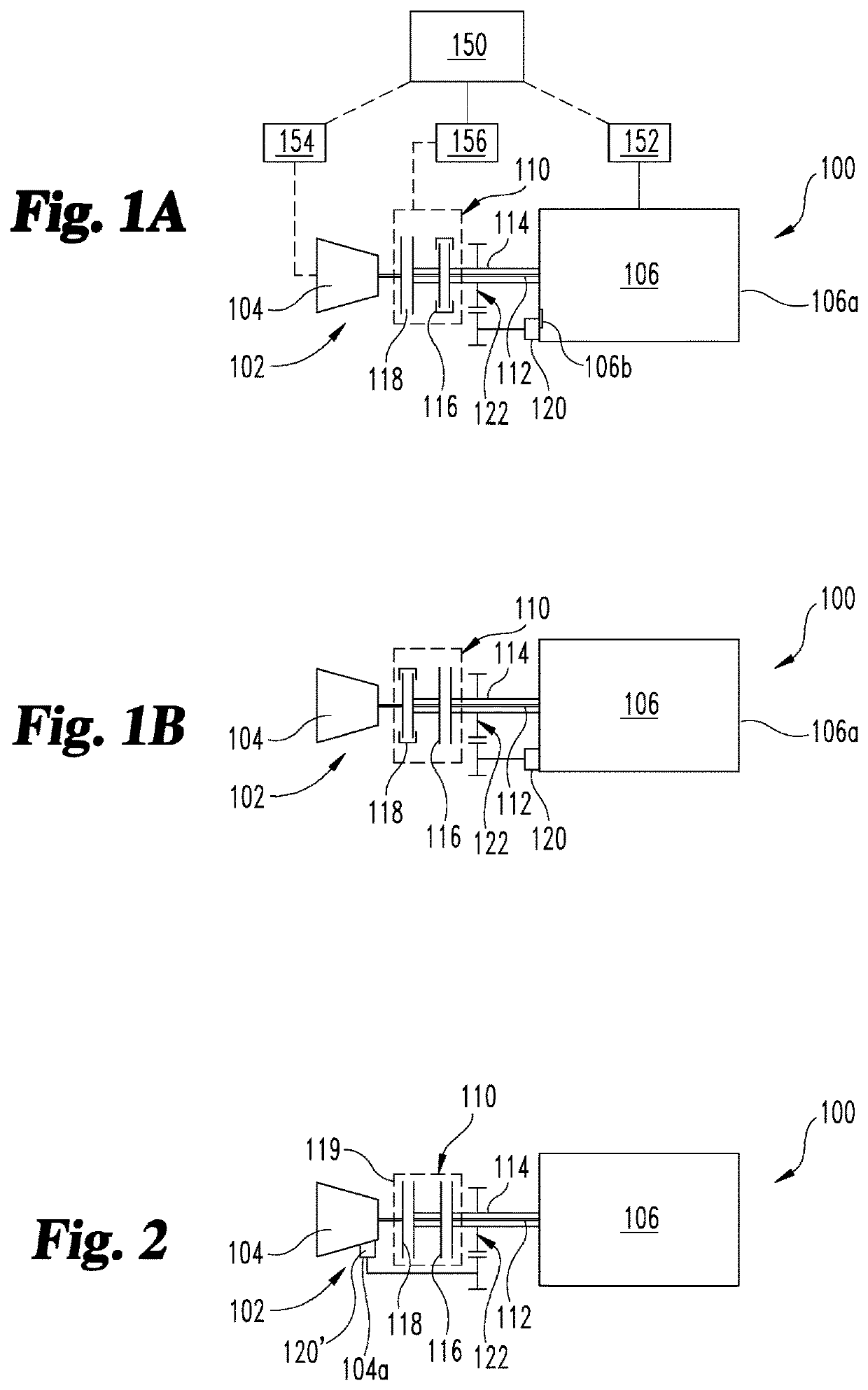
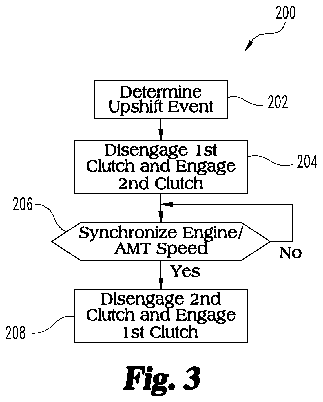
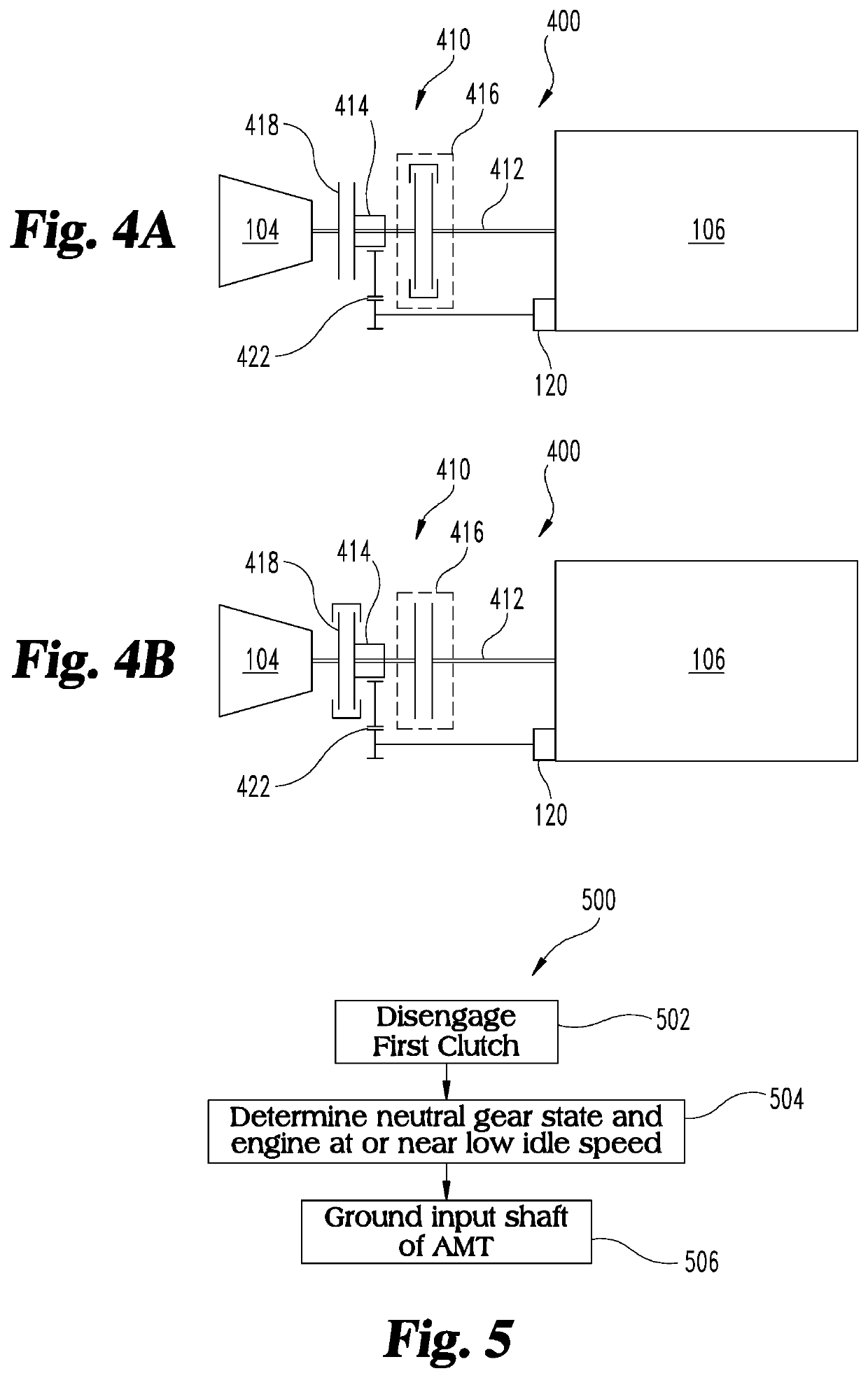
This patent describes a unique clutch assembly that can be used to connect an AMT with a prime mover. The assembly has two power paths: one controls power from the prime mover to the AMT, and the other decelerates the prime mover or AMT to synchronize their speeds for gear changes. Grounding the input shaft to the AMT reduces gear rattle and noise during idle speed conditions or during cylinder deactivation or skipfire conditions. The technical effects of this clutch assembly include improved efficiency, reduced noise and vibration, and smoother gear changes.

Problems solved by technology

Current approaches to automated manual transmissions in powertrains suffer from a number of shortcomings and unmet needs.
For example, in contrast to automatic transmissions with torque converters, AMTs employ dry clutches due to, among other reasons, cost effectiveness and upshift capability.
However, compared to automatic transmissions with torque converters, the torque interrupts associated with an AMT make execution of gear changes more difficult in some situations, such as at low speeds, and in particular on steep grades or soft road surfaces.
Furthermore, AMTs have reduced low speed maneuverability and lower capability to creep for extended durations due to the inability of dry clutches to dissipate heat and the tendency to be more prone to wear.
This practice makes the use of a wet clutch infeasible with an AMT given it has inherently higher drag as compared to a traditional dry clutch when in the open or released state.

Method used


Image

  • Clutch assembly for automated manual transmission
  • Clutch assembly for automated manual transmission
  • Clutch assembly for automated manual transmission

Examples


Embodiment Construction

[0005]For the purposes of clearly, concisely and exactly describing illustrative embodiments of the present disclosure, the manner, and process of making and using the same, and to enable the practice, making and use of the same, reference will now be made to certain exemplary embodiments, including those illustrated in the figures, and specific language will be used to describe the same. It shall nevertheless be understood that no limitation of the scope of the invention is thereby created and that the invention includes and protects such alterations, modifications, and further applications of the exemplary embodiments as would occur to one skilled in the art.

SUMMARY OF THE DISCLOSURE

[0006]Exemplary embodiments include unique apparatus, methods, systems and techniques for a clutch assembly with dual power paths and at least one wet clutch that can be used for connection of an AMT with a prime mover. One power path controls power flow from the prime mover to the AMT, and the other p...


PUM


Abstract

A system, method and apparatus are disclosed for a clutch assembly for an automated manual transmission. The clutch assembly includes a dual power path. One power path connects a prime mover to the automated manual transmission via a wet clutch, and a second power path connects one of the prime mover and the automated manual transmission to a grounded connection for synchronizing the speed thereof for a gear change.

Description

CROSS-REFERENCE TO RELATED APPLICATION[0001]The present application is a continuation of PCT Application No. PCT / US20 / 59629 filed on Nov. 9, 2020, which claims the benefit of the filing date of U.S. Provisional App. No. 62 / 935,206 filed on Nov. 14, 2019, which are incorporated herein by reference.BACKGROUND[0002]The present application relates generally to clutch assemblies for automated manual transmissions (“AMT”) and related apparatuses, methods, systems, and techniques.[0003]Current approaches to automated manual transmissions in powertrains suffer from a number of shortcomings and unmet needs. For example, in contrast to automatic transmissions with torque converters, AMTs employ dry clutches due to, among other reasons, cost effectiveness and upshift capability. However, compared to automatic transmissions with torque converters, the torque interrupts associated with an AMT make execution of gear changes more difficult in some situations, such as at low speeds, and in particul...

Claims


Application Information

Patent Timeline
Patent Type & Authority Applications(United States)
IPC IPC(8): F16H61/688F16H61/04
CPCF16H61/688F16H2061/0422F16H2306/18F16H61/0403F16H2061/0411F16H2061/0407F16H2061/0414F16H61/682F16D2500/1083F16D2500/3067F16D2500/30808F16D2500/7041
Inventor BELLINGER, STEVEN M.
Owner CUMMINS INC
Learn More