Loudspeaker placement visualizer system

a loudspeaker and visualizer technology, applied in the direction of signaling systems, instruments, transducer details, etc., can solve the problems of slow and costly trial and error to get the best acoustic coverage, undesirably expensive computer models of each venue, and difficult acoustic installation in buildings, especially auditoriums, malls,

Active Publication Date: 2020-02-18
MITEK
View PDF5 Cites 1 Cited by
  • Summary
  • Abstract
  • Description
  • Claims
  • Application Information

AI Technical Summary

Problems solved by technology

Acoustic installations in buildings, especially auditoriums, malls, concert halls, and acoustic venues generally, are made difficult because the exact sound dispersion angle of the loudspeakers is difficult to visualize.
As a result, slow and costly trial and error must be used to get the best acoustic coverage for the venue.
Alternatively, undesirably expensive computer models of each venue may be made and simulations run to determine the desired loudspeaker placement.

Method used


Image

  • Loudspeaker placement visualizer system
  • Loudspeaker placement visualizer system
  • Loudspeaker placement visualizer system

Examples


Embodiment Construction

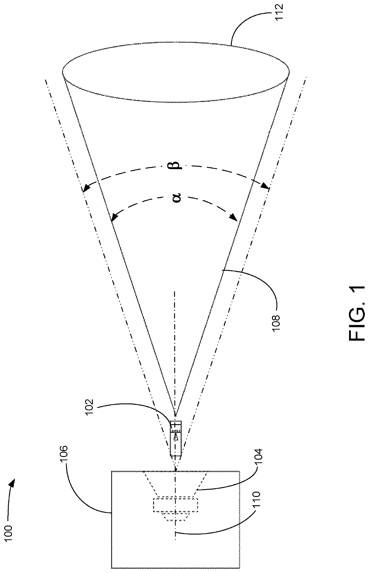
[0025]FIG. 1 is a side diagrammatic view illustrating an exemplary embodiment of a loudspeaker placement visualizer system 100, according to a preferred embodiment of the present invention. Speaker placement visualizer system 100 includes an adjustable laser beam tool 102, a loudspeaker 104 having a predetermined sound dispersion angle β, a loudspeaker cabinet 106, and brackets. Adjustable laser beam tool 102 emits a laser beam with a cone angle α that corresponds to the predetermined sound dispersion angle β of the loudspeaker 104 in speaker cabinet 106. The illustrated separation between the sound dispersion angle β and the cone angle α is exaggerated for clarity of the drawing. In practice, the sound dispersion angle β and the cone angle α are closely aligned. Speaker 104 has a central axis 110 to which the long axis 212 (see FIG. 2) of adjustable laser beam tool 102 may be aligned, as shown. Adjustable laser beam tool 102 draws a circular pattern 112 on the sound system installa...


PUM


Abstract

A loudspeaker placement visualizer system includes a calibrated adjustable laser beam tool that can generate a beam cone angle corresponding to the predetermined sound dispersion angle of a loudspeaker. The tool is secured parallel to the central axis of the loudspeaker and adjusted to the predetermined sound dispersion angle to show what the acoustic coverage area of the loudspeaker will be in a particular venue. The laser beam projector has a cylindrical main body with an external reference indicator and a forward section that is rotatable relative to the main body to adjust the laser beam cone angle. The forward section has a calibrated scale proximate the reference indicator to enable the user to set and to see the beam cone angle. The tool may also be used during venue survey and acoustic design to determine the required sound dispersion angle of a loudspeaker to be installed.

Description

FIELD OF ART[0001]The present invention relates to an apparatus for visualizing the sound dispersion of an audio loudspeaker. The present invention more particularly relates to a laser beam tool with an adjustable beam cone angle that matches the predetermined sound dispersion angle of the loudspeaker.BACKGROUND OF THE INVENTION[0002]Acoustic installations in buildings, especially auditoriums, malls, concert halls, and acoustic venues generally, are made difficult because the exact sound dispersion angle of the loudspeakers is difficult to visualize. As a result, slow and costly trial and error must be used to get the best acoustic coverage for the venue. Alternatively, undesirably expensive computer models of each venue may be made and simulations run to determine the desired loudspeaker placement.SUMMARY OF THE INVENTION[0003]The present invention provides a compact adjustable laser beam tool with an adjustable beam cone angle that is calibrated and can be selected by the user to ...

Claims


Application Information

Patent Timeline
Patent Type & Authority Patents(United States)
IPC IPC(8): H04R29/00G08B5/36
CPCH04R29/001G08B5/36H04R1/028H04R1/403H04R5/02H04R29/008H04R2205/024H04R2227/00
Inventor IVEY, JOHNATHAN
Owner MITEK
Why Eureka
Try Eureka