Liquid jetting apparatus including purge mechanism

a technology of liquid jetting apparatus and purge mechanism, which is applied in printing and other directions, can solve the problems of ink discharge in vain or wasteful, unnecessary purging, etc., and achieve the effect of not increasing the viscosity of the liquid inside the nozzl

Active Publication Date: 2020-02-25
BROTHER KOGYO KK
View PDF8 Cites 0 Cited by
  • Summary
  • Abstract
  • Description
  • Claims
  • Application Information

AI Technical Summary

Benefits of technology

Here, even in a case that empty suction for discharging the ink from the cap is performed after the purge in the above-described printer, the ink remains to some extent in the inside of the cap. In the ink remaining in the cap, the water content is evaporated, for example, at a time of the printing during which the cap does not cover the nozzle, which in turn reduces the water content in the remaining ink (increases the evaporation rate of the water content). Normally, an ink contains a humectant for suppressing the evaporation of the water content. Accordingly, in a case that the nozzle is covered by the cap in a state that the evaporation rate of the water content is high in the ink inside the cap, the humectant in the ink inside the cap absorbs the water content of the ink inside the nozzle. This lowers, as a result, the effect of suppressing the increase in viscosity of the ink inside the nozzle which is obtained by covering the nozzle with the cap.
Considering the above-described situation, an object of the preset teaching is to provide a liquid jetting apparatus which is capable of suppressing, as much as possible, a discharge amount of liquid, which is to be discharged before performing a jetting, for a purpose of realizing a stable jetting of the liquid from the nozzle onto a jetting medium as an object for the jetting.
In view of this situation, in the present teaching, under a condition that the purge condition with respect to the capping time and the value of the capping-time parameter is satisfied in a case that the jetting instruction is input, the jetting operation is performed after the purge has been performed. With this, in a case that the viscosity of the liquid inside the nozzle is high, the jetting operation can be performed after discharging the highly viscous liquid inside the nozzle by the purge performed prior to the jetting operation. On the other hand, in a case that the viscosity of the liquid inside the nozzle is not increased much, it is possible to prevent the liquid from being discharged unnecessarily from the liquid jetting head, by performing the jetting operation without performing the purge.

Problems solved by technology

As a result, there is such a fear that the purge might be performed unnecessarily and the ink might be discharged in vain or wastefully.

Method used


Image

  • Liquid jetting apparatus including purge mechanism
  • Liquid jetting apparatus including purge mechanism
  • Liquid jetting apparatus including purge mechanism

Examples


Embodiment Construction

In the following, an embodiment of the present teaching will be explained, with reference to the drawings as appropriate.

<Overall Configuration of Printer>

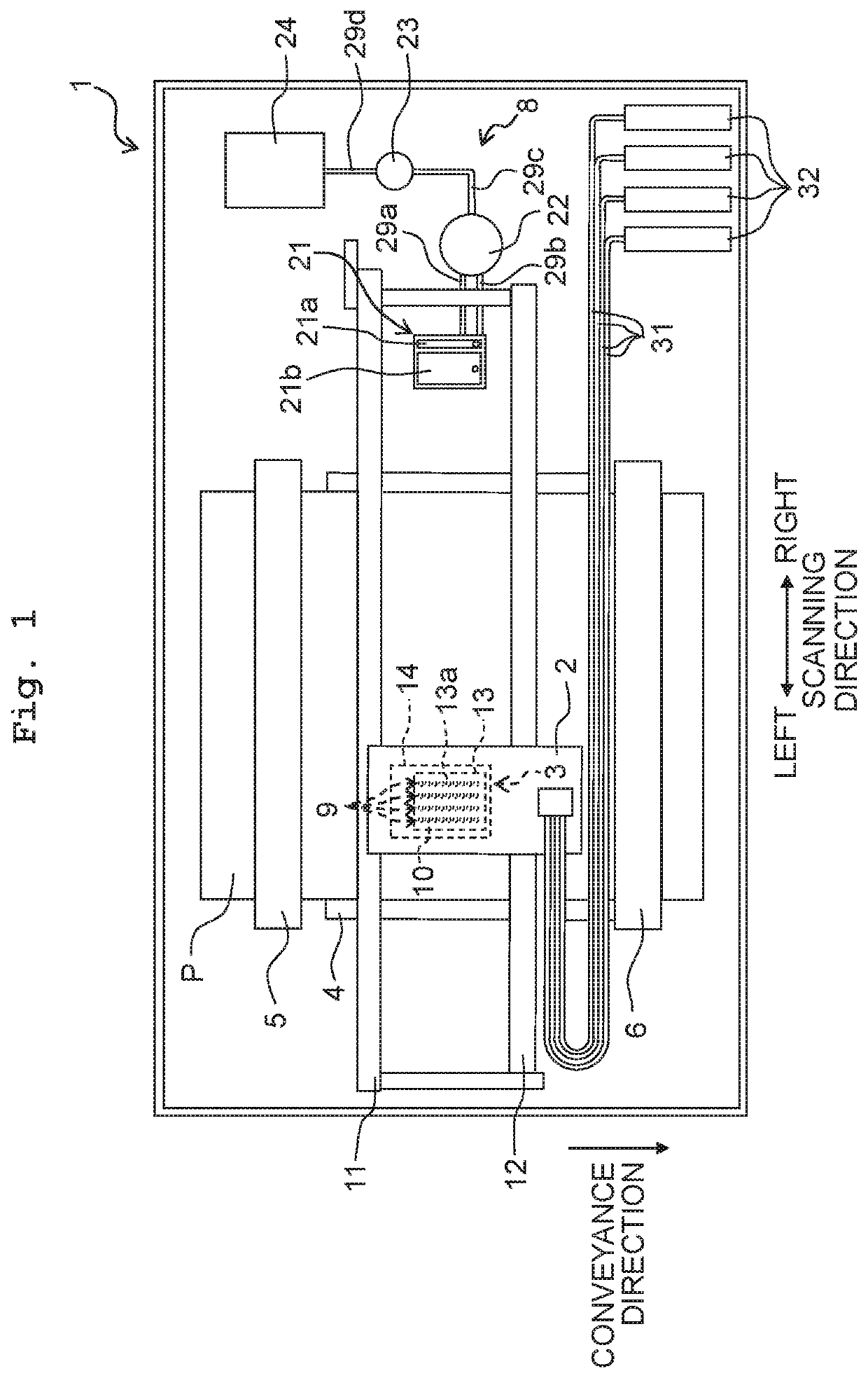
As depicted in FIG. 1, a printer 1 according to an embodiment of the present teaching (corresponding to a “liquid jetting apparatus” of the present teaching) is provided with a carriage 2, an ink-jet head 3 (corresponding to a “liquid jetting head” of the present teaching), a platen 4, conveyance rollers 5 and 6, a flushing foam 7, a maintenance unit 8, etc.

The carriage 2 is supported by two guide rails 11 and 12 extending in a scanning direction. Further, the carriage 2 is connected to a carriage motor 56 (see FIG. 2) via a non-illustrated belt, etc.; in a case that the carriage motor 56 is driven, the carriage 2 is thereby reciprocated in the scanning direction along the guide rails 11 and 12. Note that in the following explanation, the right and left sides in the scanning direction are defined as the right and left sides d...


PUM


Abstract

There is provided a liquid jetting apparatus including: a liquid jetting head; a cap; a switching mechanism configured to perform switching of a state of the cap between a capping state and an uncapping state; a timer; a purge mechanism; and a controller. The controller performs: calculating a value of a capping-time parameter; and measuring a capping time with the timer. In a case that a purge condition regarding the capping time and the value of the capping-time parameter is satisfied, the controller causes the purge mechanism to perform a purge, and then causes the liquid jetting head to perform a jetting operation.

Description

CROSS REFERENCE TO RELATED APPLICATIONThe present application claims priority from Japanese Patent Application No. 2017-189856 filed on Sep. 29, 2017, the disclosures of which are incorporated herein by reference in its entirety.BACKGROUNDField of the InventionThe present disclosure relates to a liquid jetting apparatus which jets liquid from a nozzle.Description of the Related ArtAs an example of a liquid jetting apparatus which jets liquid from a nozzle, there is a publicly known printer which jets an ink from a nozzle so as to perform printing. In this publicly known printer, a purge is performed for causing the ink to be discharged (jetted) from the nozzle into a cap. Further, in the publicly known printer, the nozzle is covered by the cap in a stand-by state in which no printing is performed, thereby suppressing the increase in viscosity of the ink inside the nozzle.SUMMARYHere, even in a case that empty suction for discharging the ink from the cap is performed after the purge ...

Claims


Application Information

Patent Timeline
Patent Type & Authority Patents(United States)
IPC IPC(8): B41J2/165
CPCB41J2/16505B41J2/16508B41J2/16517B41J2/16526B41J2002/16573
Inventor IIDA, SHOTARO
Owner BROTHER KOGYO KK
Why Eureka
Try Eureka