Resource allocation

a technology for telecommunications networks and resources, applied in multi-programming arrangements, program control, instruments, etc., can solve problems such as inefficiency, change in the requirements of individual client systems, and increase the complexity of this problem, so as to reduce the overhead of reconfiguration, and reduce the complexity of datacentre services

Active Publication Date: 2020-02-25
BRITISH TELECOMM PLC
View PDF5 Cites 4 Cited by
  • Summary
  • Abstract
  • Description
  • Claims
  • Application Information

AI Technical Summary

Benefits of technology

The invention provides a controller for the delivery of datacentre services in geo-distributed infrastructures supporting “cloud-based” services. It considers the dependencies that exist between virtual datacentre components, and aims to optimize the delivery of datacentre service in geo-distributed cloud infrastructures by minimising latencies between components in virtual datacentres, minimising reconfiguration overheads, and reducing operational and management complexity.
The invention maps the client systems to the physical datacentres' existing capabilities, rather than adapting the individual physical datacentres' capabilities to the changing requirements of the client systems to which they have been previously allocated: thus the capabilities, and not the mappings, are maintained and the mappings, not the capabilities, are dynamic, so as to optimise the allocation of client systems to cells. Reconfiguration and migration of virtual datacentre components (i.e. virtual machines) takes place only if the re-optimization of the existing Virtual Service Cells cannot satisfy the changed demand profiles. The overhead incurred in transferring virtual datacentre components across the network due to changing demand profiles is greatly reduced and the network is used mainly for end-user traffic. The risk of corrupting the state of virtual datacentre components as a result of continuous reconfiguration is also reduced. A constraint is implemented to ensure the complete virtual datacentre for each datacentre service can only be delivered from one Virtual Service Cell (i.e. one physical cloud service provider datacentre) reduces the complexity of the system and minimises the number of sessions to be maintained per enterprise request.
The invention therefore aims to reallocate the mapping of client systems to physical datacenters according to the existing capabilities of the physical datacenters, rather than reconfiguring the physical datacentres themselves to meet the changing needs of the client systems. Thus existing dependencies between virtual datacenter components are considered and key performance requirements such as minimal latency between components in virtual datacentres can be maintained and reconfiguration costs avoided.

Problems solved by technology

The complexity of this problem increases if there are dependencies that need to be taken into consideration.
A problem arises when the requirements of individual client systems change over time.
However, this leads to communications inefficiencies and additional latency (delay) as data has to be exchanged between multiple physical datacentres to service individual requests.
However, reconfiguration requires setup, migration (maintaining and transferring virtual machine state and data), and teardown of cloud-based services, and this is a complex process, and may require shut-down and / or the availability of temporary storage whilst the reconfiguration takes place.

Method used


Image

  • Resource allocation
  • Resource allocation
  • Resource allocation

Examples


Embodiment Construction

The first and second sets of demand profiles referred to above are specified in detail in Table 1 later in this description.

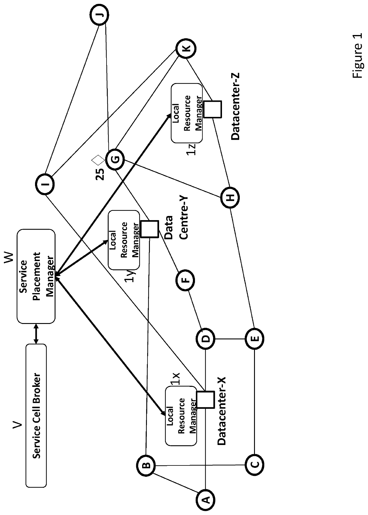
FIG. 1 depicts the architecture of a geo-distributed cloud infrastructure having three datacentres X, Y, Z, and a number of network access nodes (labelled A to K) through which individual client systems communicate with the datacentres. Each data centre has a respective local resource management system 1x, 1y, 1z, whose operations are coordinated by a service placement manager W controlled by a Service Cell Broker V operating according to the invention, and as will be described with reference to FIGS. 3, 4 and 5.

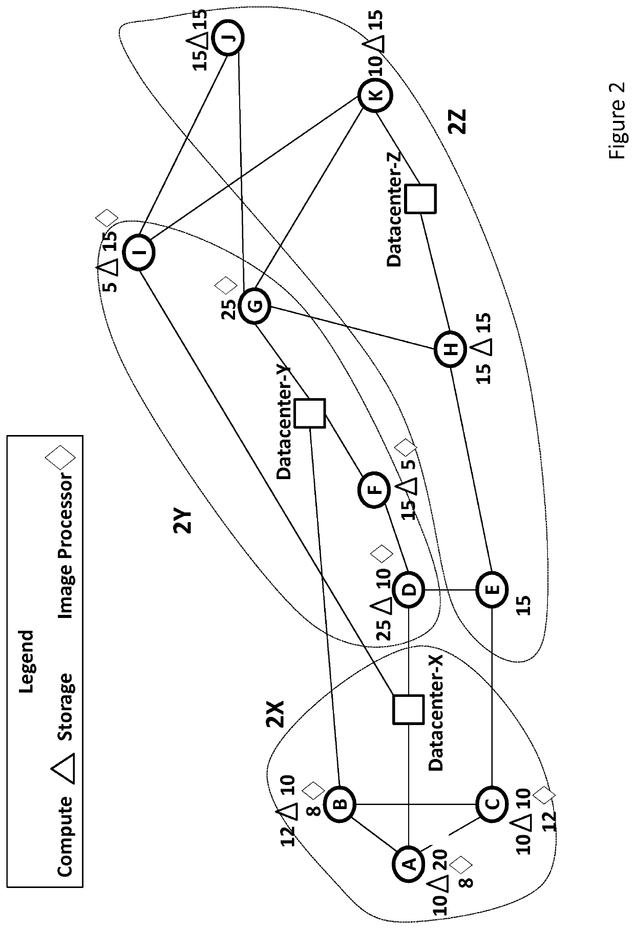
FIG. 2 depicts an allocation of the network access nodes (A-K) of FIG. 1 to cells X, Y, Z, according to the requirements of the client systems of each node (A-K). For the purposes of illustration, each node has been assigned a set of service requirements, indicated by symbols as listed in the legend of FIG. 2, the numerical value associated with each sy...


PUM


Abstract

As data processing requirements of individual client systems A to K change over time, they are allocated service from physical datacentres X, Y, Z according to the existing capabilities of the data centres requirements of the client systems, thus transferring client systems between cells controlled by individual data centres. This avoids the complex process of adapting the individual physical datacentres' capabilities to the changing requirements of the client systems to which they were originally allocated: thus the capabilities, and not the mappings, are maintained and the mappings, not the capabilities, are dynamic, so as to optimise the allocation of client systems to cells. It also minimises the number of clients having to work to more than one datacentre, which leads to delays in processing as the datacentres need to communicate with each other.
Configuration of the datacentres X, Y, Z themselves is required to set up the system, but subsequently only if a re-optimization of the existing mappings cannot satisfy the changed demand profiles, for example because the overall balance of services available from the datacentres no longer matches the services required.

Description

This application is the U.S. national phase of International Application No. PCT / EP2015 / 078955 filed Dec. 8, 2015 which designated the U.S. and claims priority to EP Patent Application No. 14275259.1 filed Dec. 16, 2014, the entire contents of each of which are hereby incorporated by reference.BACKGROUND AND SUMMARYThis invention relates to allocation and provisioning of resources in a telecommunications network, and in particular optimisation of service cell allocation in a virtualised (“cloud-based”) datacentre system. However, although the embodiments of the invention will be described with reference to such a cloud-based system, the allocation and provisioning process may have applications in wider fields and no limitation of the scope of the invention is implied by discussion of details of the embodiments.The provision of cloud-based datacentre services allows enterprises to be offered complete virtual datacentres with data processing resources such as computing, storage, and i...

Claims


Application Information

Patent Timeline
Patent Type & Authority Patents(United States)
IPC IPC(8): G06F15/173H04L29/08G06F9/50
CPCH04L67/1012H04L67/327H04L67/30H04L67/322G06F9/5077H04L67/1021H04L67/61H04L67/63
Inventor NTOFON, OKUNGOWUSU, GILBERTSHAKYA, SIDDHARTHA
Owner BRITISH TELECOMM PLC
Why Eureka
Try Eureka