
Sterilizing system

a sterilizing system and sterilizing agent technology, applied in the field of sterilizing systems, can solve the problems of the sterilizing agent being removed and the risk of the sterilizing agent remaining in the cap, and achieve the effect of reducing the amount of oxygen used

Active Publication Date: 2020-03-03
SUNTORY HLDG LTD
View PDF11 Cites 0 Cited by
  • Summary
  • Abstract
  • Description
  • Claims
  • Application Information

AI Technical Summary

Benefits of technology

[0005]To cope with the above, the present inventors have discovered a novel method according to which a sterilizing device configured to sterilize a sterilization-subject article without risks of remaining of sterilizing agent on the sterilization-subject article such as a cap to be fitted on a bottle, etc. is used to generate plasma and reactive oxygen produced by reacting the plasma with steam and the plasma are used for effecting sterilization. Reactive oxygen dies out over time, so it will not remain. Moreover, sterilization using reactive oxygen does not require application of such heat which may cause thermal contraction of the sterilization-subject article. Therefore, by using this method that effects sterilization with a sterilizing agent containing plasma and reactive oxygen, it is possible to avoid residual of the sterilizing agent on the sterilization-subject article and occurrence of excessive thermal contraction / deformation of the sterilization-subject article. However, since this method is novel, sufficient contemplation has not yet been made, respecting an efficient operation of a sterilization system using this method.

Problems solved by technology

However, removal of sterilizing agent entirely by means of cleaning is difficult, so there is a risk of the sterilizing agent remaining in the cap.

Method used


Image

  • Sterilizing system
  • Sterilizing system
  • Sterilizing system

Examples


first embodiment

[0031][First Embodiment]

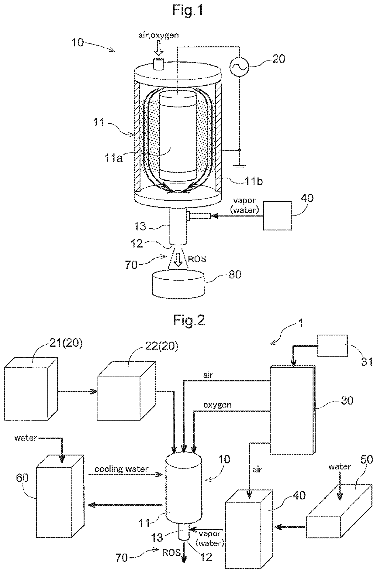
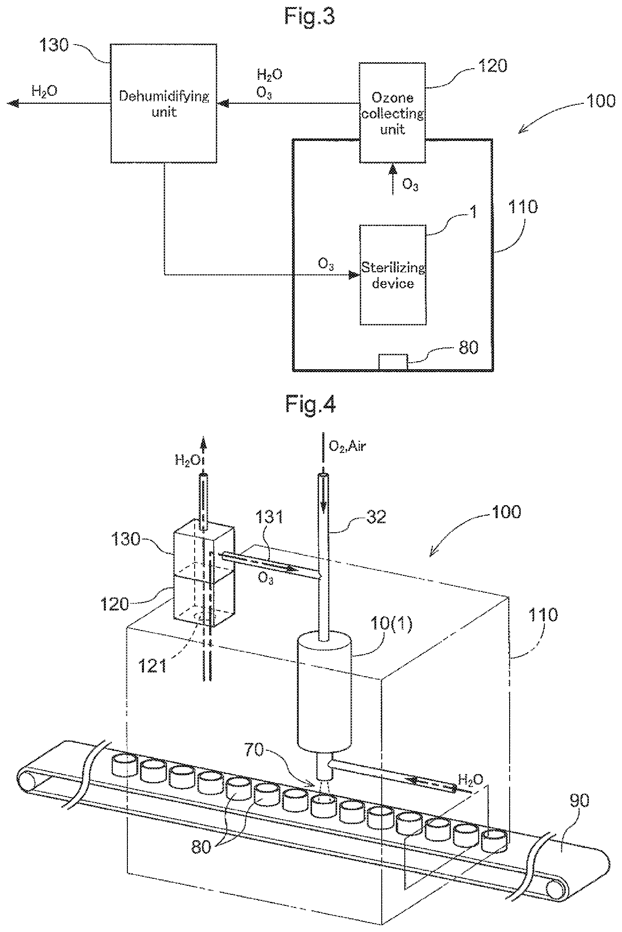
[0032]Next, an embodiment of a sterilizing system relating to the present invention will be explained with reference to the accompanying drawings. A sterilizing system 100 according to the instant embodiment is provided for sterilizing, as an example of a sterilization-subject article, a cap 80 of a container such as a PET bottle. And, the sterilizing system 100 includes a sterilizing device 1 configured to generate plasma and to sterilize the cap 80 by the obtained plasma. The sterilizing device 1 receives supply of oxygen and steam. The sterilizing device 1 produces oxygen plasma containing ozone from the supplied oxygen and discharges a sterilizing agent containing the produced plasma and reactive oxygen (reactive oxidizing species (ROS), e.g. OH radical or singlet oxygen, etc.) produced from a reaction between the supplied steam and the produced plasma, thus sterilizing the cap 80. Then, firstly, there will be explained the device configuration of the ste...

second embodiment

[0053][Second Embodiment]

[0054]A second embodiment of the sterilizing system relating to the present invention will be explained with reference to the accompanying drawings. In this embodiment, the destination of ozone gas collected by the ozone collecting unit 120 differs from the first embodiment. Next, the sterilizing system relating to this embodiment will be explained, respecting mainly its difference from the first embodiment. Incidentally, respecting those aspects not explicitly described, they are same as the first embodiment and denoted with the same reference marks / numerals; and explanation thereof will be omitted.

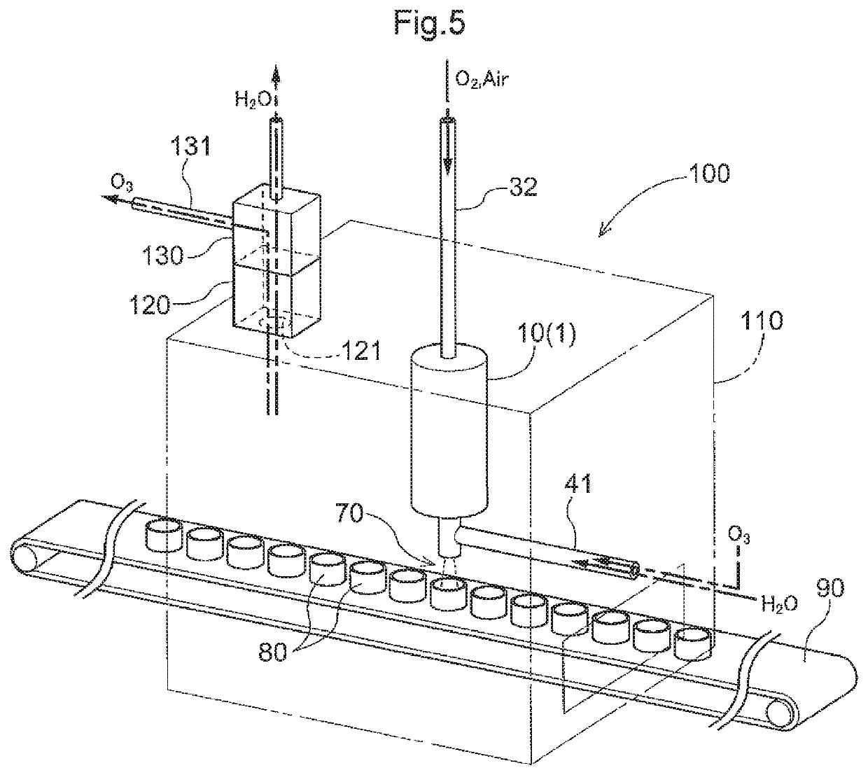
[0055]In the sterilizing system 100 shown in FIG. 5 and relating to this embodiment, the conductive passage 131 for ozone gas after dehumidification by the dehumidifying unit 130 is connected to a steam supplying passage 41 for supplying steam from the evaporator 40 (incidentally, in FIG. 5, the connecting portion between the ozone gas conductive passage 131 and ...


PUM

PropertyMeasurementUnit
frequencyaaaaaaaaaa
currentaaaaaaaaaa
voltageaaaaaaaaaa

Abstract

In a sterilizing system, a sterilizing device receives supply of oxygen and steam. The sterilizing device produces oxygen plasma containing ozone from the supplied oxygen and discharges the produced oxygen plasma and reactive oxygen produced through reaction between the supplied steam and the oxygen plasma as a sterilizing agent. And, the sterilizing system includes an ozone collecting unit for collecting ozone contained in the discharged oxygen plasma.

Description

TECHNICAL FIELD[0001]This disclosure relates to a sterilizing system configured to sterilize a sterilization-subject article such as a cap of a container.RELATED ART[0002]As a method of sterilizing a cap of a container such as a PET bottle as one example of a sterilization-subject article, there is known a sterilizing method disclosed in Japanese Unexamined Patent Application Publication No. 2013-28398 (Patent Document 1). Patent Document 1 discloses a method of effecting sterilization of an inside of the container by discharging a sterilizing agent containing hydrogen peroxide into the bottle or its cap.[0003]In the case of employing a sterilizing agent containing hydrogen peroxide as implemented in the technique of Patent Document 1, it is necessary to effect cleaning subsequently in order not to allow the sterilizing agent to remain in the cap. However, removal of sterilizing agent entirely by means of cleaning is difficult, so there is a risk of the sterilizing agent remaining i...

Claims


Application Information

Patent Timeline
Patent Type & Authority Patents(United States)
IPC IPC(8): A61L2/14A61L2/20A61L2/00A61B18/04
CPCA61L2/14A61L2/20A61B18/042A61L2/0011A61L2202/14A61L2202/11A61L2202/122A61L2209/212
Inventor HIGASHIYAMA, KENICHITOMINAGA, KENTAHIRAYAMA, YUJIYOSHIHARA, KAZUKIIIZUKA, TOSHIAKIMORIYA, SATOSHI
Owner SUNTORY HLDG LTD
Learn More