
Toilet flushing device

a technology for toilets and toilets, applied in toilets, water installations, constructions, etc., can solve the problems of many inconveniences during the operation of the toilet, leakage and inefficiency of the water used, and bending laterally

Inactive Publication Date: 2013-07-04
PRECIADO VILLANUEVA JOSE JAIME +1
View PDF0 Cites 5 Cited by
  • Summary
  • Abstract
  • Description
  • Claims
  • Application Information

AI Technical Summary

Benefits of technology

The present invention provides a toilet flushing device that can prevent leakage into the outlet pipe, efficiently flush water from the cistern to the outlet pipe, have easily replaceable components, have a simple construction, and provide a better user experience.

Problems solved by technology

Older devices like the flap valve or more recently the siphon flush apparatuses are described in the prior art; however, the majority of them show leakages and inefficiencies in the way of water is used.
The main problem that the flushing devices have to face until now is the leakage.
For example, the conventional flap valve or tank ball is very effective for fast flushing water but due to its design and materials, it has many inconveniences during its operation.
Nevertheless, it has the inconvenient that when the water is filling the cup, it does not sink the way it is described and nonetheless the presence of the guide-rod, when the assembly is falling down, it bends laterally, choking all the way down because the flexible sleeve does not have the proper reinforcements.
Another disadvantage is that due the guide-rod is located in the center of the flexible sleeve and supported at the access of the outlet pipe, it reduces the overall efficiency of the assembly making the flushing process more complex.
Likewise, the flushing process is too weak making it useless to discharge the water with enough force.
There is described the presence of a guide-rod for avoiding lateral bending of the flexible tube, but as the device of U.S. Pat. No. 815,661, it has the inconvenient that the guide-rod reduces the efficiency of the flushing apparatus.
Likewise due the upper cup is made of rubber, it is probably that the buoyancy force will not be enough to raise all the assembly.
The mechanism used to apply down force to the upper cup is complex and requires periodical maintenance in order to work properly and finally, due the sinking process of the upper cup is very slow, the flush generated does not have enough force to discharge the water properly.
The main disadvantage of the above mentioned device is its impossibility of being adapted in older toilets which has the handle aperture in the front wall of the toilet cistern.
Moreover, to successfully accomplish the discharge process, the user has to remain pushing down the handle until near all water from the cistern has been flushed otherwise the process is interrupted and not completed.
An inherent problem of this kind of system is that the toilet cistern cap never has the exactly same position, so if the cap for any reason is moved and replaced, the guide housing became crooked causing the malfunction of the entire system.
However, as we can see from the prior art, the siphon flush effect is less efficient than the traditional method because it has more wastes so the siphon flush apparatus of above requires a higher amount of water in every discharge.

Method used


Image

  • Toilet flushing device
  • Toilet flushing device
  • Toilet flushing device

Examples


Embodiment Construction

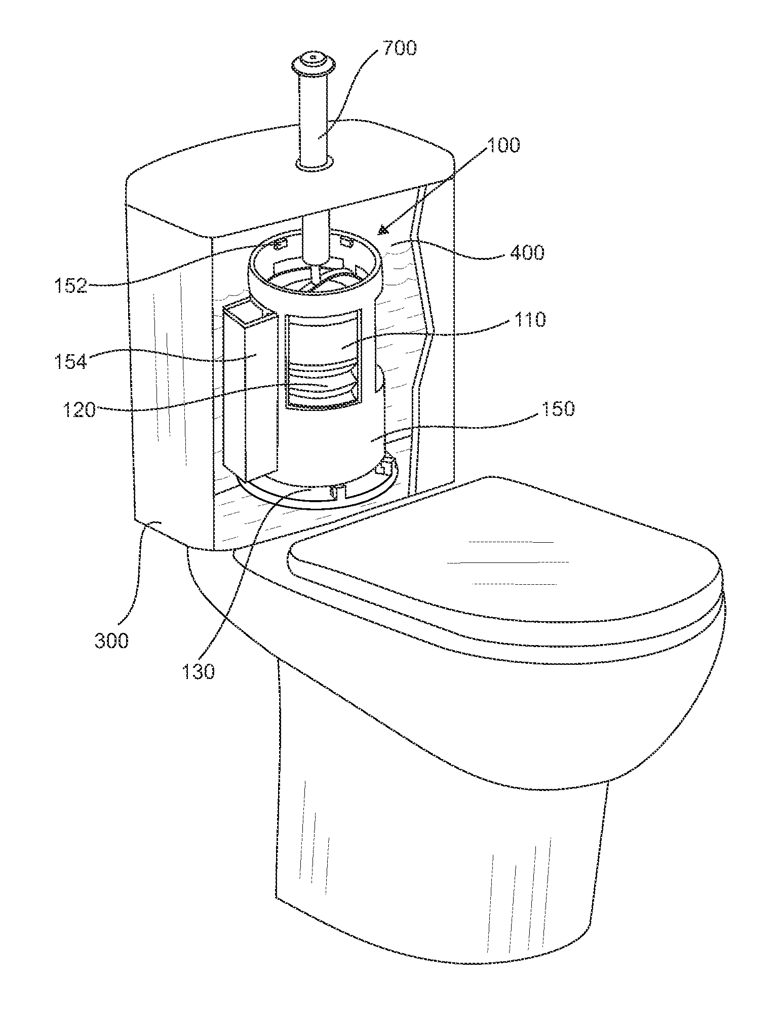
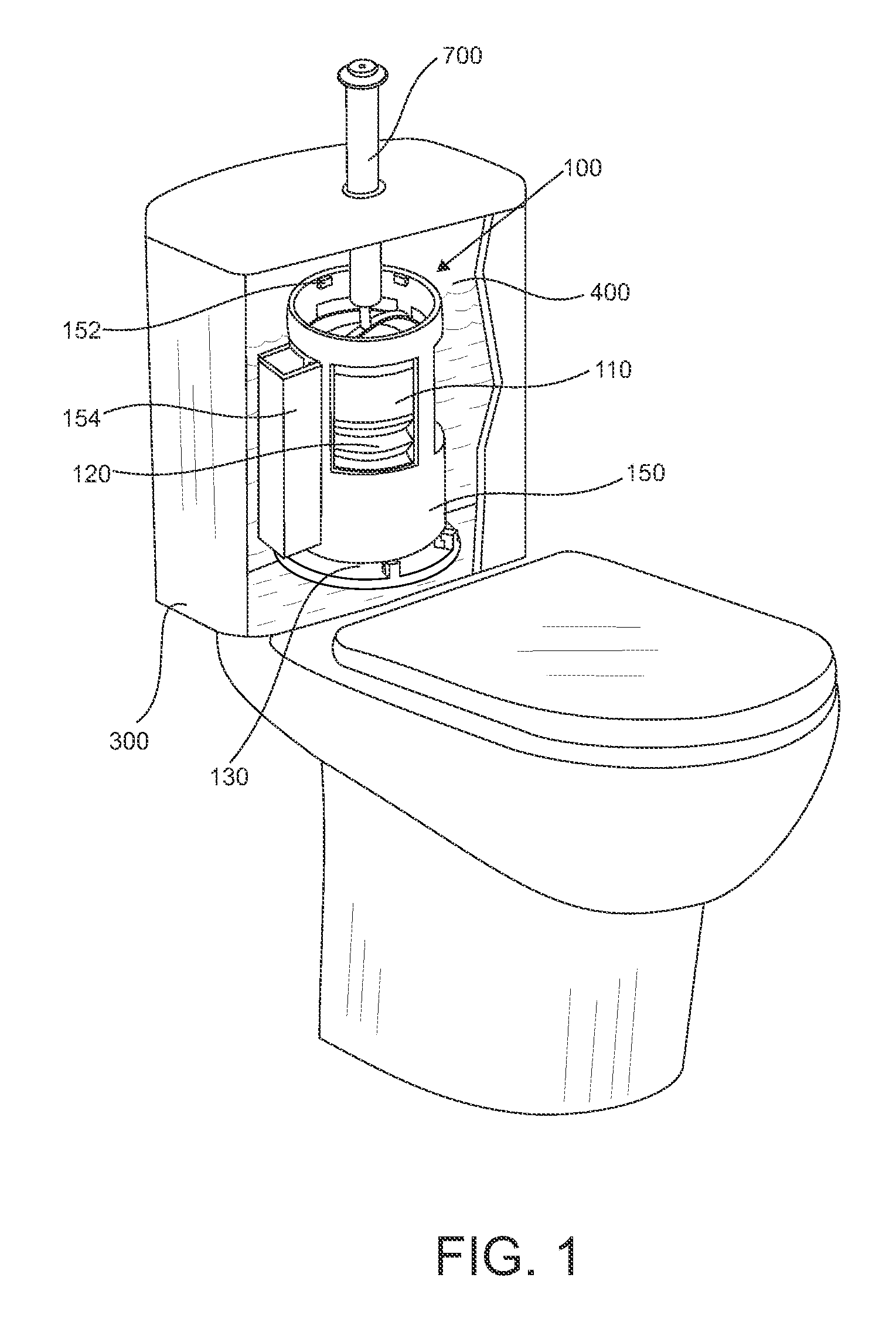
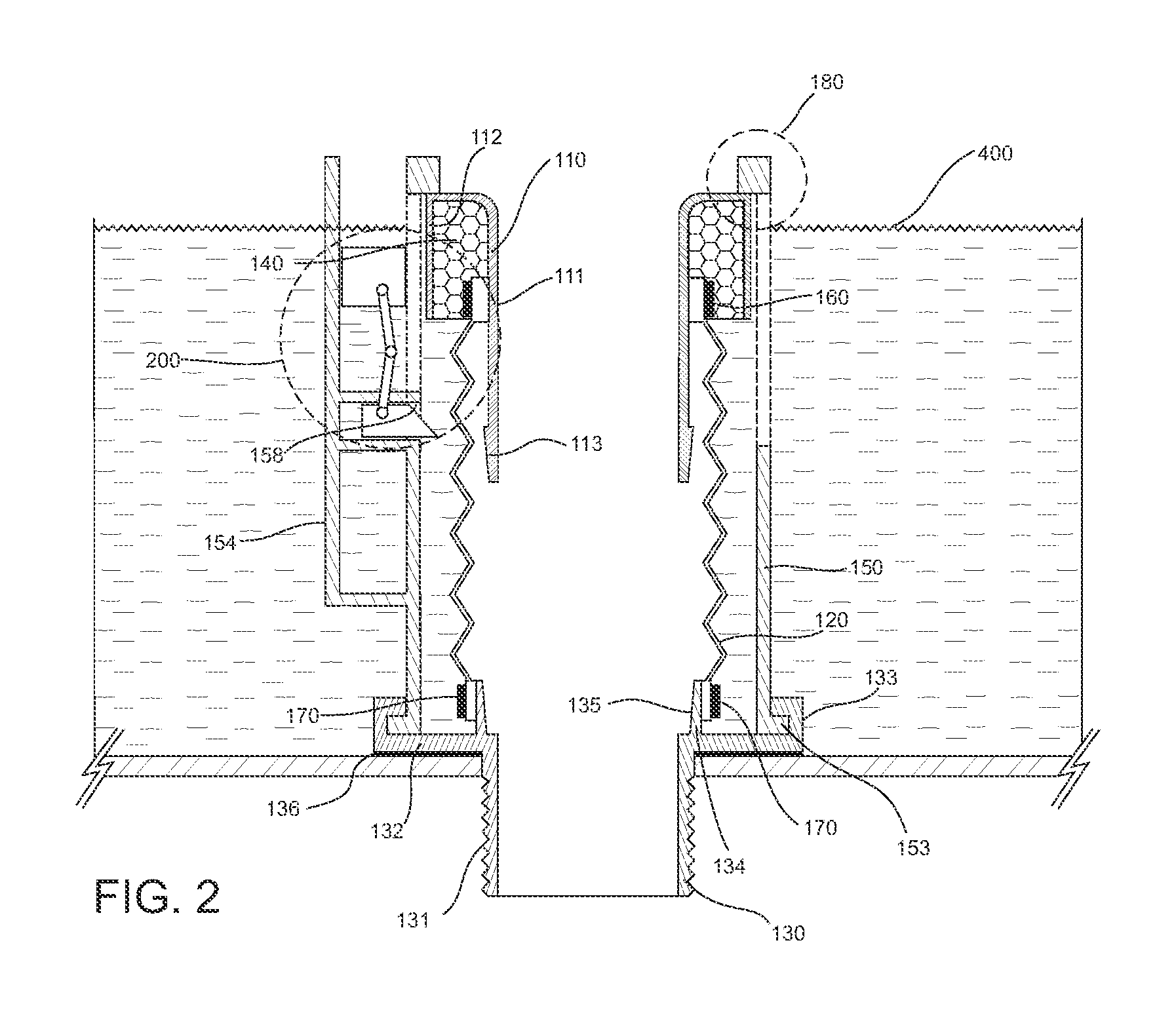
[0040]Having now more particular reference to the drawings and more specifically FIG. 1 to FIG. 3 there is shown a preferred embodiment of the toilet flushing device 100 of the present invention located inside the toilet cistern at its rest position. The toilet flushing device 100 comprises a sliding conduct 110 extending upwardly and rising above the maximum water level 400 into a cistern 300; a flexible sleeve 120 interconnected to the sliding conduct 110 and to a base support 130; a base support 130 extending upwardly and downwardly from beyond the bottom surface of the cistern 300; floating means 140 for moving the sliding conduct 110 upwards along the inner wall of an external guide cylinder 150; first fixing means 160 for fixing the flexible sleeve 120 to the sliding conduct 110; second fixing means 170 for fixing the flexible sleeve 120 to the base support 130; an external guide cylinder 150 having a length enough to rise above maximum water level 400 into the cistern 300, sa...


PUM


Abstract

A toilet flushing device including a sliding conduct extending upwardly and rising above the maximum water level into a cistern; a flexible sleeve; a base support extending from beyond the bottom surface of the cistern; a floating mechanism for moving the sliding conduct upwards along an external guide cylinder; a first fixing mechanism fixing the flexible sleeve to the sliding conduct; a second fixing mechanism fixing the flexible sleeve to the base support; the external guide cylinder having a length sufficient to rise above maximum water level into the cistern; a first stopping mechanism for preventing the sliding conduct from moving upwardly beyond the external guide cylinder; a second stopping mechanism for preventing the sliding conduct from descending beyond the base support; and, a detention system for maintaining the sliding conduct at the bottom of the cistern until the water level reaches a predefined level.

Description

FIELD OF THE INVENTION[0001]The present invention is related with the techniques and devices used for flushing cisterns, and more particularly, it is related to a toilet flushing device.BACKGROUND OF THE INVENTION[0002]It is well known that there are many kinds of devices used to flush water from the cisterns of the toilets. Older devices like the flap valve or more recently the siphon flush apparatuses are described in the prior art; however, the majority of them show leakages and inefficiencies in the way of water is used. The main problem that the flushing devices have to face until now is the leakage. For example, the conventional flap valve or tank ball is very effective for fast flushing water but due to its design and materials, it has many inconveniences during its operation. It is submitted to strengths and to the chemical action of the water (chlorine, high mineral content, etc.) which causes deformations and modifications in its geometry, causing the flap valve does not a...

Claims


Application Information

Patent Timeline
Patent Type & Authority Applications(United States)
IPC IPC(8): E03D1/35
CPCE03D1/304E03D1/34
Inventor PRECIADO-VILLANUEVA, JOSE JAIMEPRECIADO-CHACON, ADOLFO
Owner PRECIADO VILLANUEVA JOSE JAIME
Learn More