
Magnetic chip conveyor

a conveyor and magnetic chip technology, applied in auxiliary equipment, manufacturing tools, transportation and packaging, etc., can solve the problems of long chip on the front surface and chip remains

Active Publication Date: 2019-08-08
SHOUNAN ENG
View PDF2 Cites 2 Cited by
  • Summary
  • Abstract
  • Description
  • Claims
  • Application Information

AI Technical Summary

Benefits of technology

The magnetic chip conveyor in this patent has a difference in the magnetic forces between adjacent magnets, which prevents longer chips from getting stuck in the mechanisms and ensures that they don't get left on the non-magnetic plate.

Problems solved by technology

In such a case, there is a problem in that the long chip does not move on the front surface of the non-magnetic plate and the long chip remains on the front surface of the non-magnetic plate.

Method used


Image

  • Magnetic chip conveyor
  • Magnetic chip conveyor
  • Magnetic chip conveyor

Examples


Embodiment Construction

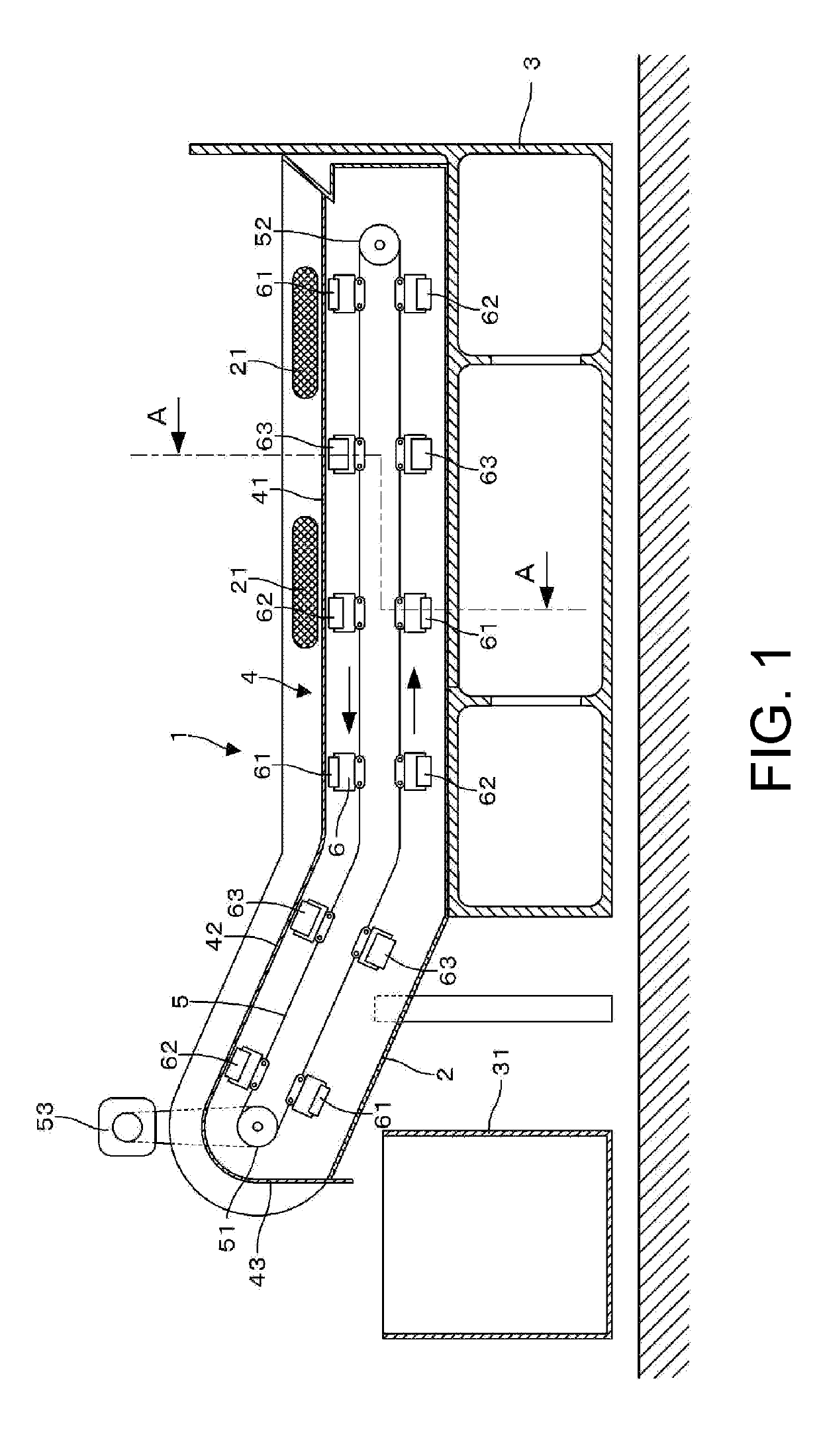
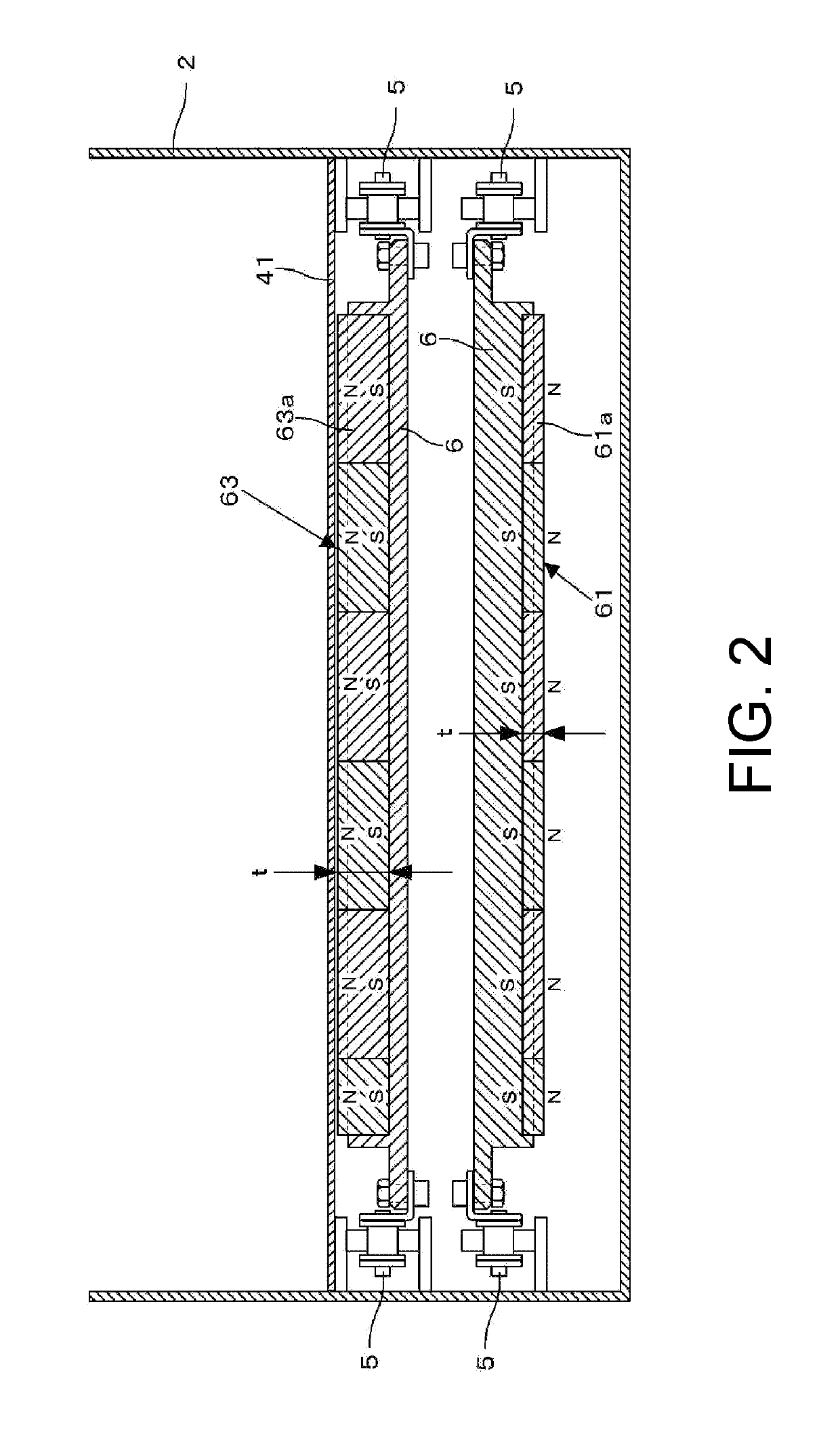
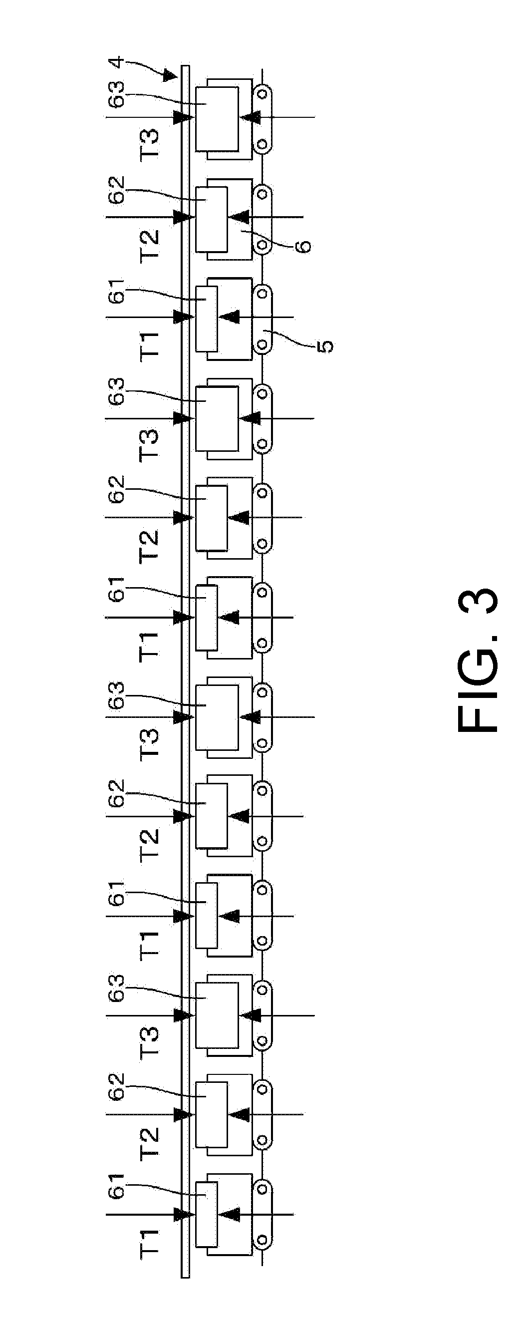
[0019]Embodiments of the present invention are described below with reference to the drawings. FIG. 1 is an overall vertical cross-sectional view illustrating a magnetic chip conveyor according to an embodiment of the present invention. FIG. 2 is a cross-sectional view taken along the line A-A in FIG. 1. FIG. 3 is an exploded view of an endless chain in FIG. 1. FIG. 4 illustrates the vicinity of a chip drop portion at a left end of a plate made of a non-magnetic material in FIG. 1. FIG. 4(a) is an enlarged vertical cross-sectional view, and FIG. 4(b) is a plan view of FIG. 4(a). A magnetic chip conveyor 1 in the embodiment of the present invention includes a box-shaped chip conveyor main body 2 elongated in the left-right direction in FIG. 1. The chip conveyor main body 2 in this example is mounted and placed on a bed 3 of a machine tool. A plate 4, which is a thin plate made of the non-magnetic material (such as SUS304) and has a smooth front surface, is integrally and fixedly disp...


PUM


Abstract

A magnetic chip conveyor of the present invention reduces the possibility that both end portions of a long chip are adsorbed by two or more types of magnets having different magnetic forces, so that a long chip does not remain. An endless chain is disposed on the rear surface of a plate, so as to be wound around sprocket wheels. The sprocket wheel is rotated in the counterclockwise direction by a motor, and the endless chain rotates in the counterclockwise direction. Twelve magnet holders are fixed to the endless chain at equal intervals. Three types of permanent magnets having different magnetic forces are bonded and fixed to the magnet holders.

Description

TECHNICAL FIELD[0001]The present invention relates to a magnetic chip conveyor. More specifically, the present invention relates to a magnetic chip conveyor for preventing a long chip such as that generated by a lathe from remaining.BACKGROUND ART[0002]Magnetic chip conveyors, which are configured such that a magnetic chip is placed on the front surface of a non-magnetic plate, a plurality of magnets mounted to an endless chain on the rear surface of the plate are moved from one end of the plate to the other end thereof so that the chip is dropped from the other end of the plate, are known (Patent Literature 1, Patent Literature 2, Patent Literature 3). Such magnetic chip conveyors are preferred because chips generated during processing can be separated from coolant and discharged and coolant is less frequently carried to the outside.[0003]In the conventional magnetic chip conveyors, however, when a long chip such as a chip generated by a lathe is generated, adsorption forces that a...

Claims


Application Information

Patent Timeline
Patent Type & Authority Applications(United States)
IPC IPC(8): B65G17/46B65G54/02B03C1/18
CPCB65G17/46B65G54/02B03C1/18B23B25/00B23Q11/00B03C1/0332B03C1/20B03C2201/20B65G54/025B65G17/02B23Q11/0042B65G2201/04
Inventor SAZAWA, MASAJI
Owner SHOUNAN ENG
Learn More