

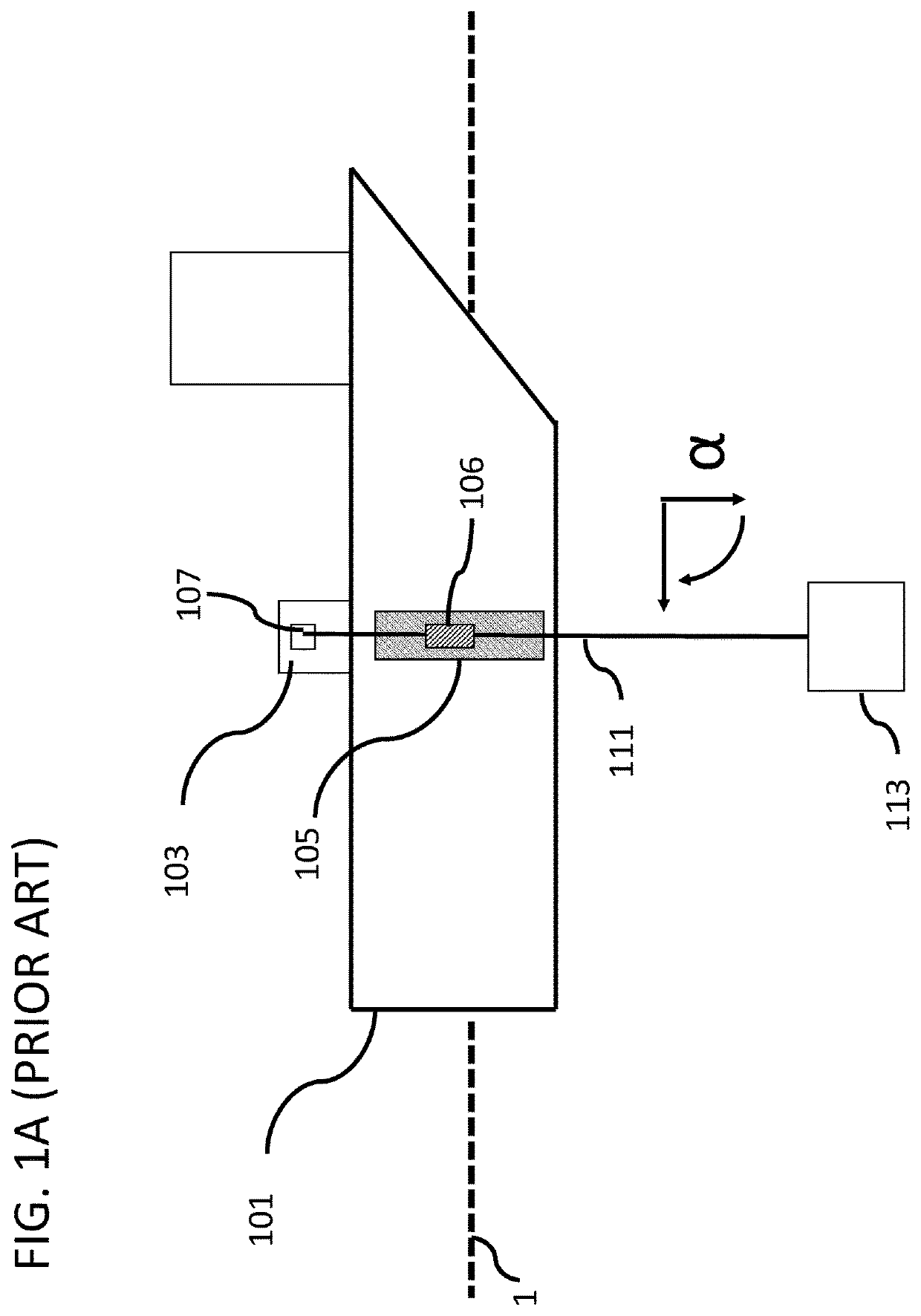
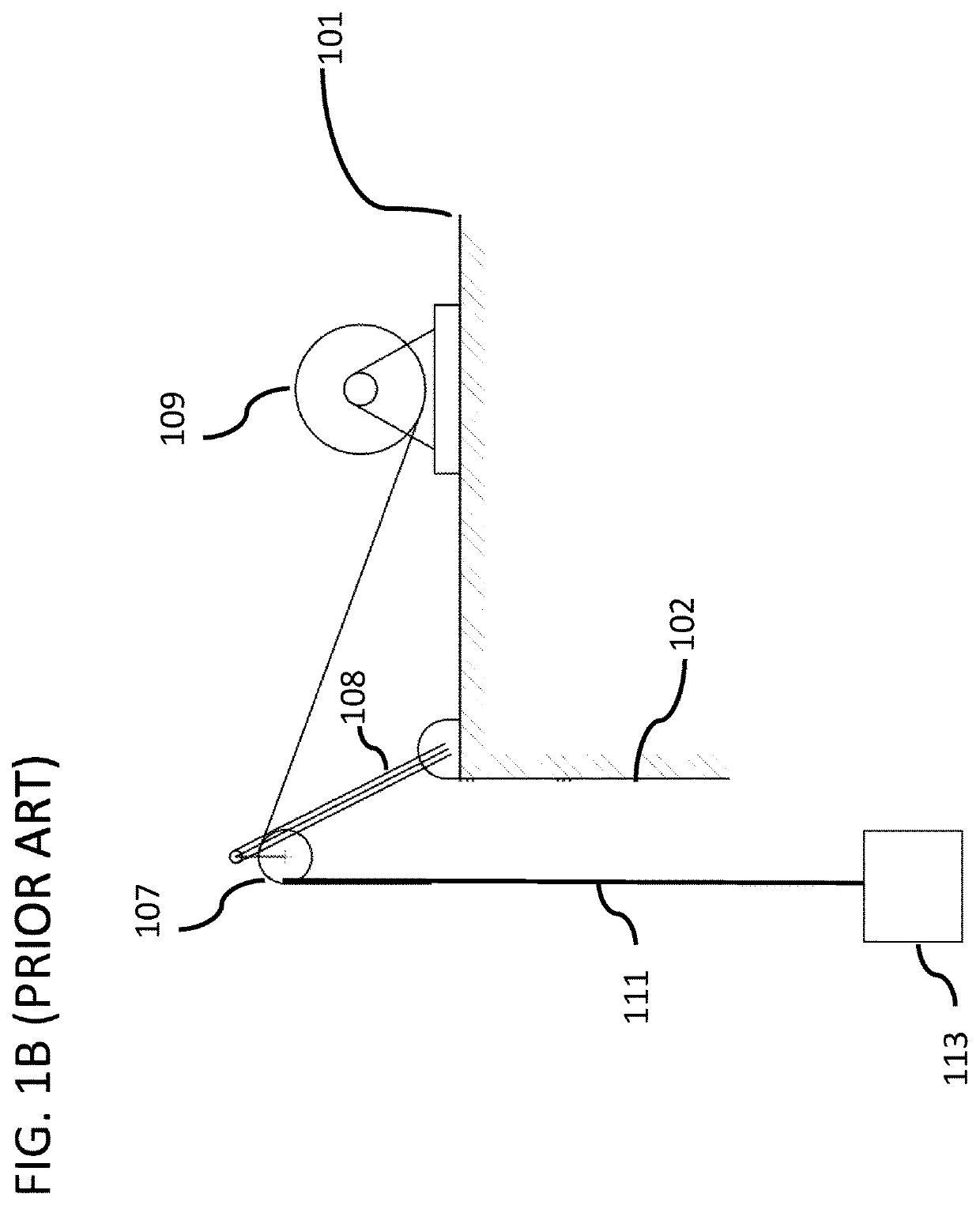
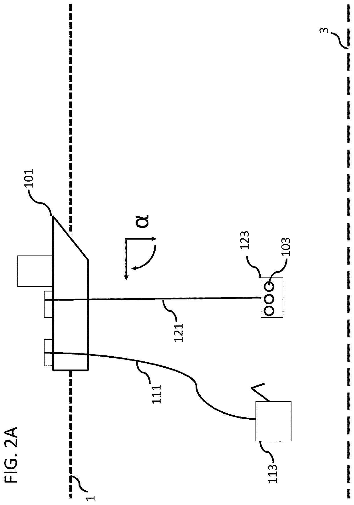
High angle deployment system for a seismic marine surface vessel
a deployment system and seismic marine technology, applied in underwater equipment, special-purpose vessels, vessel construction, etc., can solve the problems of reducing the overall speed of the survey, the surface vessel cannot operate above a particular speed or deploy equipment at a certain depth or direction, and the existing system cannot tolerate much more than a 15-degree angle for the deployment cable. achieve the effect of higher deployment angl
- Summary
- Abstract
- Description
- Claims
- Application Information
AI Technical Summary
Benefits of technology
Problems solved by technology
Method used
Image

Examples
Embodiment Construction
[0023]Various features and advantageous details are explained more fully with reference to the nonlimiting embodiments that are illustrated in the accompanying drawings and detailed in the following description. Descriptions of well known starting materials, processing techniques, components, and equipment are omitted so as not to unnecessarily obscure the invention in detail. It should be understood, however, that the detailed description and the specific examples, while indicating embodiments of the invention, are given by way of illustration only, and not by way of limitation. Various substitutions, modifications, additions, and / or rearrangements within the spirit and / or scope of the underlying inventive concept will become apparent to those skilled in the art from this disclosure. The following detailed description does not limit the invention.
[0024]Reference throughout the specification to “one embodiment” or “an embodiment” means that a particular feature, structure, or charac...
PUM
 Abstract
Description
Claims
Application Information