Compressor control device, compressor control system, and compressor control method

a compressor and control device technology, applied in the direction of engines, mechanical equipment, machines/engines, etc., can solve the problem of how the load of each compressor is determined

Active Publication Date: 2020-03-10
MITSUBISHI HEAVY INDUSTIES COMPRESSOR CORP
View PDF19 Cites 87 Cited by
  • Summary
  • Abstract
  • Description
  • Claims
  • Application Information

AI Technical Summary

Benefits of technology

[0019]According to the above-described aspects of the present invention, in a system in which a plurality of gas turbines and a plurality of fuel gas compressors are provided, it is possible to assign loads to the compressors regardless of the numbers of gas turbines and compressors.

Problems solved by technology

However, in the case of a system in which a plurality of gas turbines and a plurality of fuel gas compressors are provided, when the pressure of the fuel gas header is controlled, there is a problem of how a load of each compressor is determined.

Method used


Image

  • Compressor control device, compressor control system, and compressor control method
  • Compressor control device, compressor control system, and compressor control method
  • Compressor control device, compressor control system, and compressor control method

Examples


first embodiment

[0031]Hereinafter, a compressor control device according to a first embodiment of the present invention is described with reference to FIGS. 1 to 4.

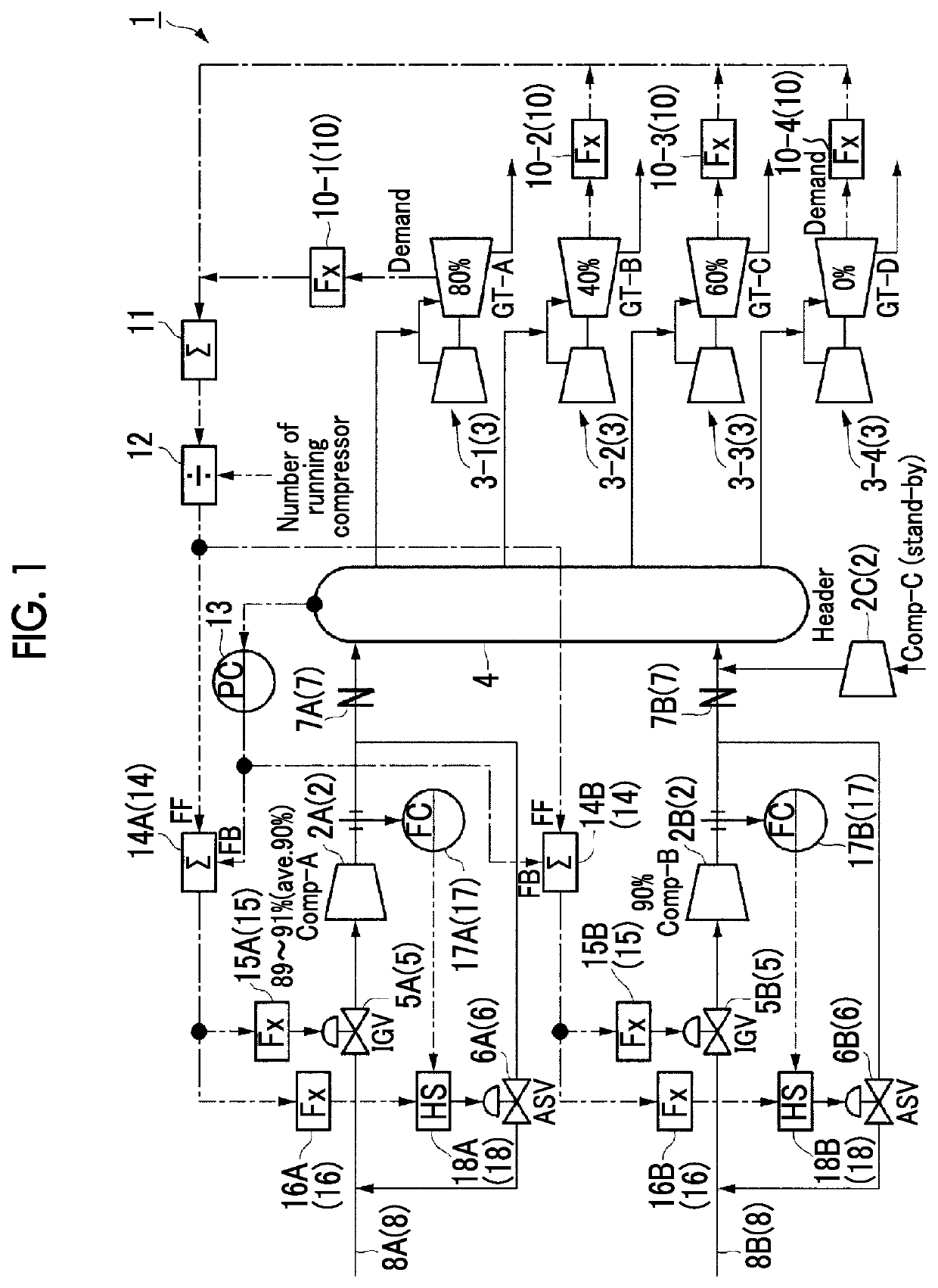
[0032]FIG. 1 is a first diagram showing an example of a configuration of a load running system according to the first embodiment of the present invention. A load running system 1 includes a plurality of compressors 2 (2A, 2B, and 2C), a plurality of gas turbines 3 (3-1, 3-2, 3-3, and 3-4), and a compressor control device 30. The number of running gas turbines 3 may be one or a multiple. In the load running system 1 of FIG. 1, three compressors 2 (2A, 2B, and 2C), four gas turbines 3 (3-1, 3-2, 3-3, and 3-4), and one compressor control device 30 are provided. In addition, the compressor 2C is a spare compressor which is not run currently. A fuel gas which is a fuel of the gas turbine 3 is supplied from the upstream side of a fuel gas supply line 8 (8A and 8B), and is supplied to the gas turbine 3 (3-1 to 3-4) via an IGV 5 (5A and 5B), the...

second embodiment

[0070]Hereinafter, a compressor control device 30 according to a second embodiment of the present invention is described with reference to FIG. 5.

[0071]In the second embodiment, the plurality of compressors 2 are controlled by one compressor control device 30 described in FIG. 1 of the first embodiment, and the second embodiment is different from the first embodiment in that the PC 13 outputs the second control signal generated by the feedback control to the operation end of each compressor 2.

[0072]FIG. 5 is a diagram showing an example of a configuration of a load running system in the second embodiment of the present invention.

[0073]As shown in FIG. 5, in the load running system 1 of the present embodiment, a divider 19 is provided in the rear stage of the PC 13. The divider 19 divides the correction amount of the operation value calculated by the PC 13 by the number of the currently running compressors 2. The divider 19 outputs the divided correction amount to the adder 14. Other...

third embodiment

[0077]Hereinafter, a compressor control device 30 according to a third embodiment of the present invention is described with reference to FIGS. 6 to 9.

[0078]The third embodiment is an embodiment with respect to the load control of the compressor 2 in a situation in which outflow of the gas from the fuel gas header is not generated before the gas turbine 3 starts or when the gas turbine stops. Moreover, in the present embodiment, the feedback control is applied to all the compressors 2.

[0079]FIG. 6 is a diagram showing an example of the configuration of the load running system in the third embodiment of the present invention. As shown in FIG. 6, in the load running system 1 according to the present embodiment, a pressure gauge 21A is provided on the downstream side of the compressor 2A, and a pressure gauge 21B is provided on the downstream side of the compressor 2B. The pressure gauge 21A and the pressure gauge 21B are connected to the high-level selector 23. In addition, similarly ...


PUM


Abstract

With regard to a load running system that comprises a plurality of compressors that compress a fuel gas and supply the compressed fuel gas to a load apparatus, this compressor control device comprises: a feedforward control signal generation unit that, on the basis of a value that is found by dividing the total load of the load apparatus by the number of running compressors, generates a first control signal that is for controlling the amount of fuel gas supplied by the compressors; and a control unit that, on the basis of the first control signal, controls the amount of fuel gas supplied by the compressors.

Description

TECHNICAL FIELD[0001]The present invention relates to a compressor control device, a compressor control system, and a compressor control method.BACKGROUND ART[0002]A fuel gas compressor for supplying a fuel gas to a gas turbine is controlled such that a pressure of a fuel gas header is constant. For example, by combining a feedforward control which uses a preceding signal on the basis of a load of the gas turbine and a feedback control on the basis of a measured value and a target value of the pressure of the fuel gas header, a supply amount of the fuel gas discharged from the compressor is adjusted, and the pressure of the fuel gas header is controlled. As means for adjusting the supply amount of the fuel gas, an Inlet Guide Vane (IGV) provided on the upstream side of a compressor, or an Anti Surge Valve (ASV) which is provided on a bypass through which the fuel gas discharged from the compressor is recirculated to the upstream side is used. A control system of the fuel gas compres...

Claims


Application Information

Patent Timeline
Patent Type & Authority Patents(United States)
IPC IPC(8): F02C9/28F02C7/36F02C3/22F02C7/22F02C9/26F02C9/50F02C6/02F02C7/236F02C9/30
CPCF02C7/236F02C9/26F02C7/22F02C9/50F02C3/22F02C7/36F02C9/28F02C9/30F02C6/02F05D2220/32F05D2270/301F05D2270/13F02C9/42
Inventor NAKAGAWA, YOSUKEYONEMURA, NAOTOJAHAMI, KAZUHIRO
Owner MITSUBISHI HEAVY INDUSTIES COMPRESSOR CORP
Why Eureka
Try Eureka