
Tag mounter

a technology of mounting brackets and mounting plates, which is applied in the field of mounting plates, can solve the problems of affecting the smooth operation affecting the quality of the mounting plate, so as to facilitate the restriction of thickness and/or types of the mounting plate. and the effect of simple structur

Active Publication Date: 2020-03-17
TOWA SEIKO
View PDF6 Cites 0 Cited by
  • Summary
  • Abstract
  • Description
  • Claims
  • Application Information

AI Technical Summary

Benefits of technology

The present invention aims to address the restrictions in thread thicknesses and types, which makes it difficult to use various threads such as a gold thread and a silver thread. The tag mounter according to the present invention can grip and retract the tip of the thread using a gripper unit, which helps in eliminating the insertion of the thread through a needle eye. This simplifies the gripping process and enables the use of various threads. Additionally, the griiller unit can grip the thread exposed from the tip of the pipe unit, ensuring easy gripping of the thread.

Problems solved by technology

Even using a thread thinner than the needle eye, the tag mounter may not smoothly work when the thread is relatively thick and / or has large friction resistance, caused by large friction with the needle eye.
Conversely, when the thread is relatively thin and / or has small strength, the friction with the needle eye may cause breaking the thread.
This results in restriction of thicknesses and / or types of available threads.

Method used


Image

  • Tag mounter
  • Tag mounter
  • Tag mounter

Examples


Embodiment Construction

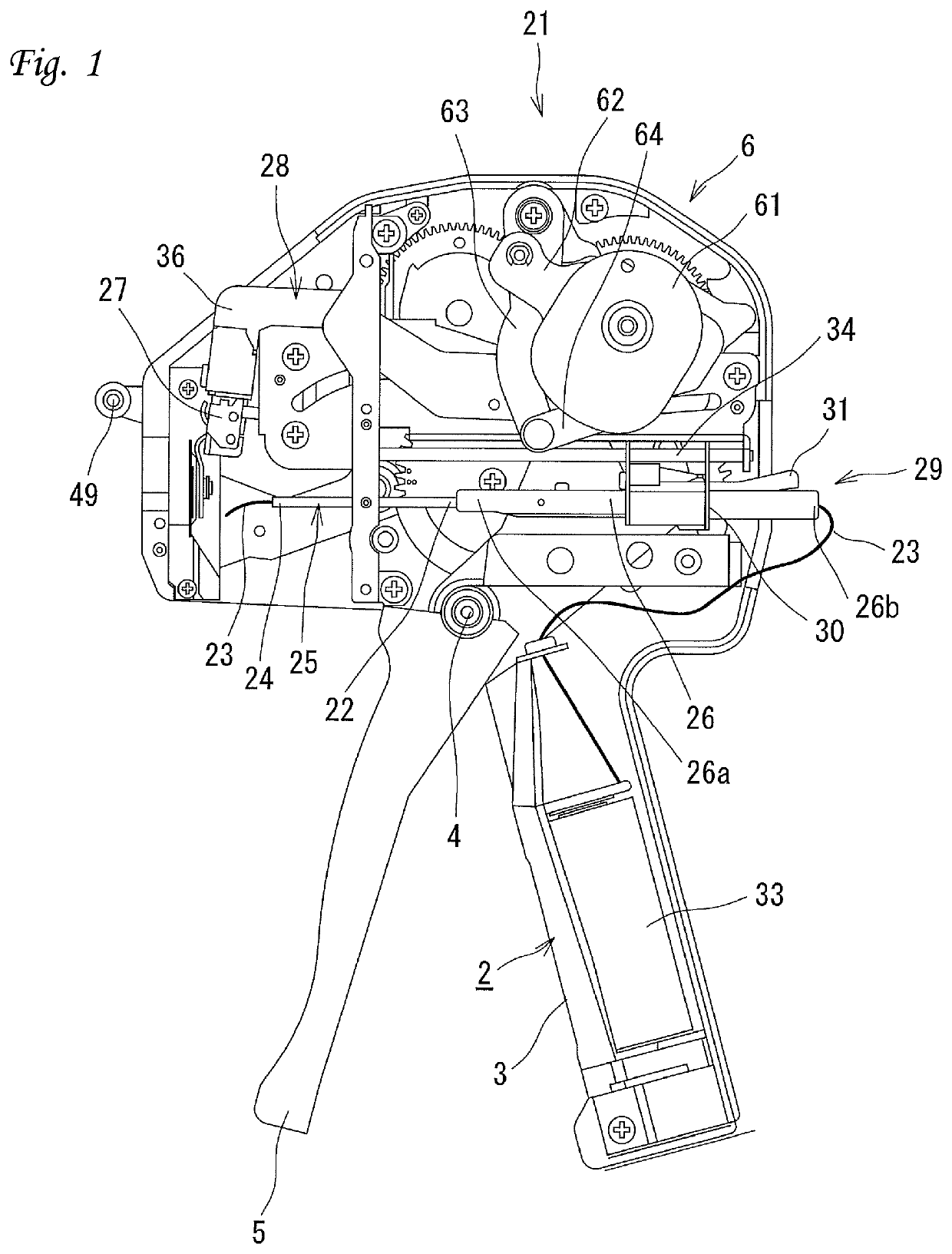
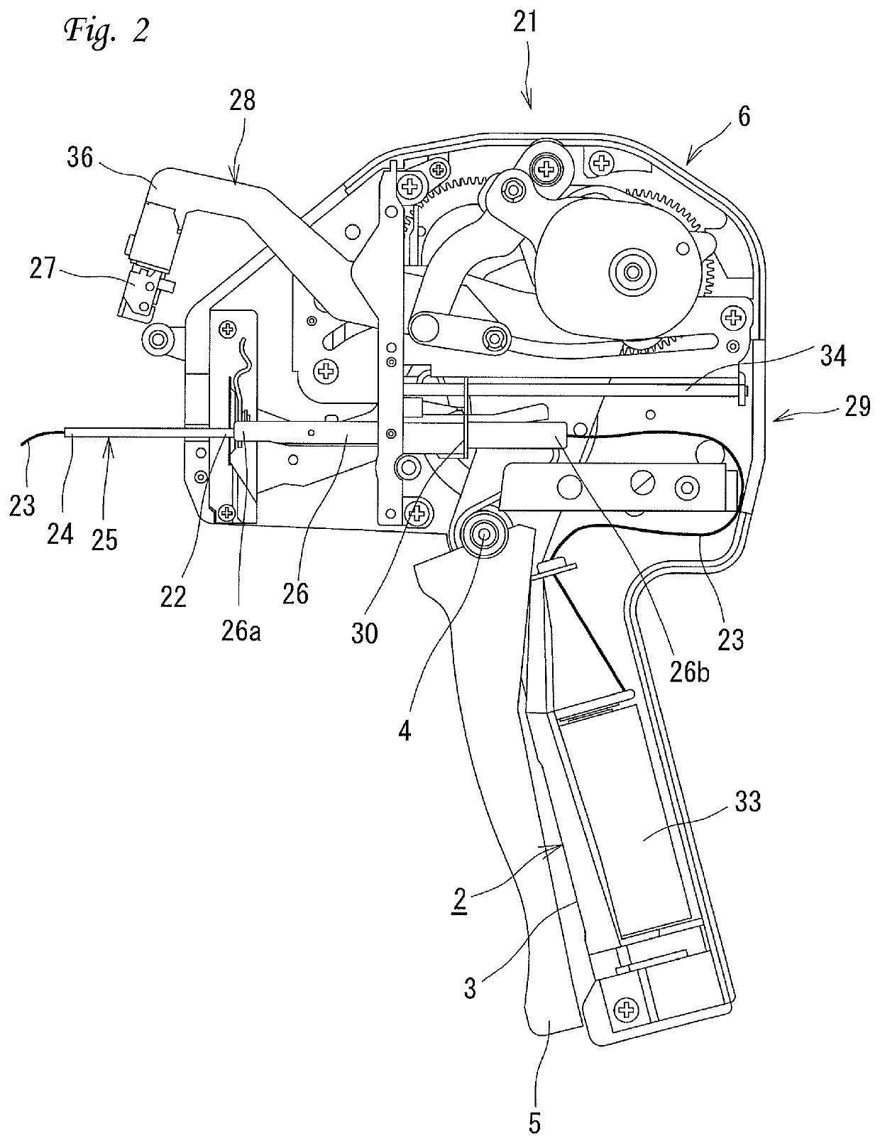
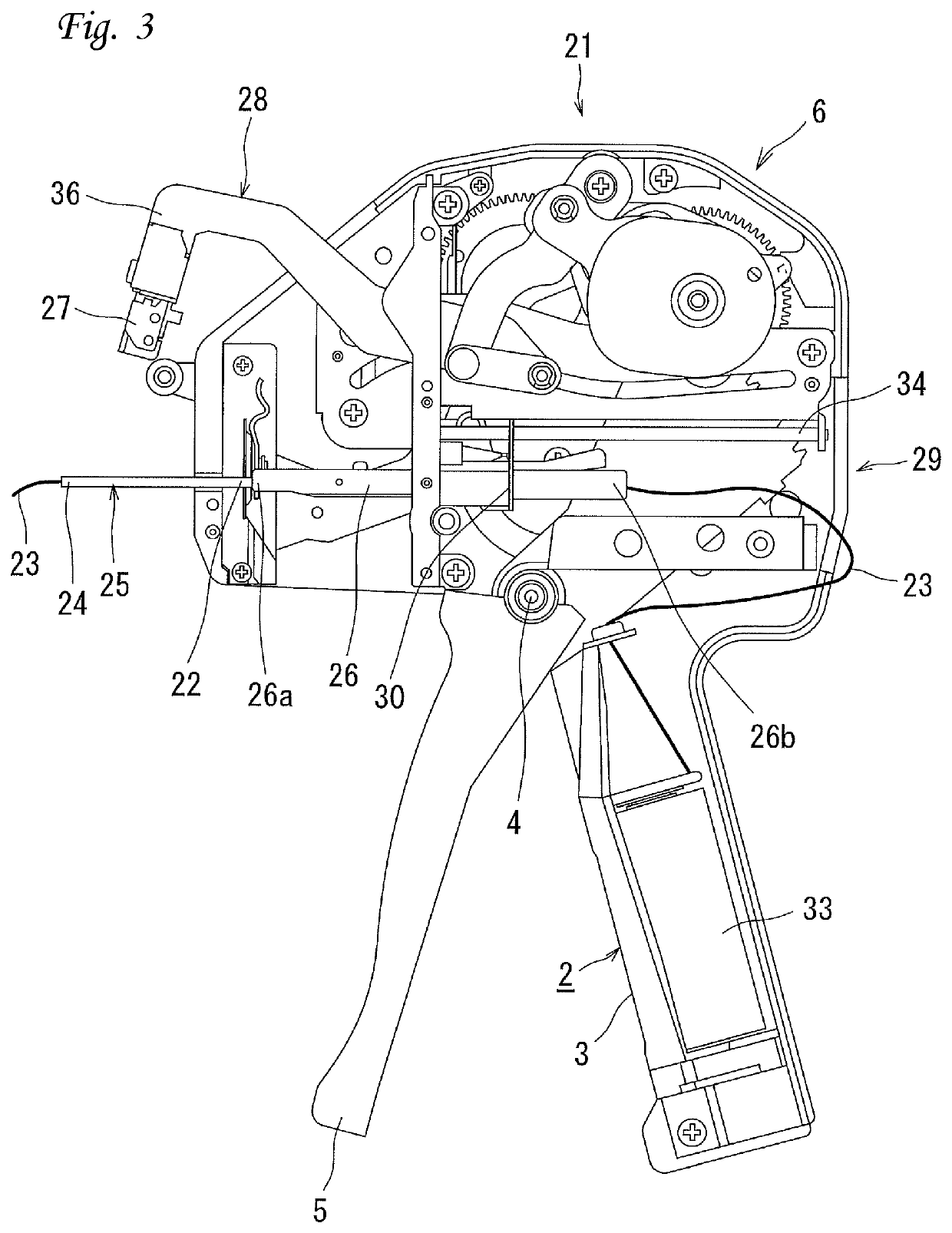
[0022]FIG. 1 shows a tag mounter 1 including a machine frame 2, a driving lever 5, and a driver unit 6. The machine frame 2 has a handle 3 protruding from it. The driving lever 5 is mounted on a base portion of the handle 3, and has capability to pivot around a lever shaft 4. Two grasping operations of the driving lever 5 makes the driver unit 6 to perform actions, which will be described below in details. A part of the machine frame 2 and some mechanisms are omitted in FIGS. 1 to 8 for explanation.

[0023]The handle 3 accommodates a bobbin 33. The bobbin 33 has a thread 23 coiled around it. The bobbin 33 has capability to rotate in the handle 3. This enables to pay out the coiled thread 23.

[0024]The machine frame 2 has a thread hanging unit 49 at its front face. The thread hanging unit 49 is for making uniformity of a size of a loop of the thread 23 formed by the tag mounter 21. The thread hanging unit 49 is a shaft substantially parallel to a left / right direction, and fixed to the m...


PUM


Abstract

A tag mounter (21) is provided for mounting a tag to an object by passing and tying a thread (23) through the object. A pipe unit (25) is configured to insert the thread (23) through it. A movement mechanism (29) is configured to move the pipe unit (25) toward a front direction and a rear direction. A gripper unit (27) is configured to grip the thread (23) inserted through the pipe unit (25) and exposed from a tip of the pipe unit (25). A driver unit (6) is configured to move the gripper unit (27) along a predetermined course. A thread tying mechanism (16) is configured to tie the thread (23) gripped by the gripper unit (27).

Description

CROSS-REFERENCE TO RELATED APPLICATIONS[0001]This application claims the benefit of and priority to Japanese Patent Application No. 2016-092406 filed on May 2, 2016, which is incorporated herein by reference in its entirety.BACKGROUND OF THE INVENTION1. Field of the Invention[0002]The present invention relates to a tag mounter.2. Description of the Related Art[0003]A tag mounter is for threading an object such as a product to mount a price tag or other tags on it.[0004]A conventional tag mounter is known as described in Japanese Examined Patent Publication No. H3-43137, filed by the Applicant of the present application, which is incorporated herein by reference in its entirety.[0005]FIGS. 11 and 12 illustrate the tag mounter 1 including a machine frame 2, a driving lever 5, and a driver unit 6. The machine frame 2 has a handle 3 protruding from it. The driving lever 5 is mounted on a base portion of the handle 3, and has capability to pivot around a lever shaft 4. Two grasping opera...

Claims


Application Information

Patent Timeline
Patent Type & Authority Patents(United States)
IPC IPC(8): B65C7/00B31D1/02
CPCB31D1/023B65C7/00B31D2201/02D05B3/20D05B35/066
Inventor KAWADA, TOSHIKAZU
Owner TOWA SEIKO
Learn More