Wide-area solid-state illumination devices and systems

a solid-state illumination and wide-area technology, applied in the direction of optics, instruments, optical light guides, etc., can solve the problems of energy waste, suboptimal performance, and difficulty in efficiently coupling, decoupling and/or dispersing light, and achieve the effect of high areal density

Active Publication Date: 2020-03-17
S V V TECH INNOVATIONS
View PDF26 Cites 7 Cited by
  • Summary
  • Abstract
  • Description
  • Claims
  • Application Information

AI Technical Summary

Problems solved by technology

The conventional edge-lit illumination systems may exhibit certain limitations such as difficulty to efficiently couple, decouple and / or distribute light.
Additionally, configuring the edge-lit illumination systems for a desired angular distribution and uniformity of the emission may be associated with optical losses and lead to energy waste and suboptimal performance.

Method used


Image

  • Wide-area solid-state illumination devices and systems
  • Wide-area solid-state illumination devices and systems
  • Wide-area solid-state illumination devices and systems

Examples


example 1

End of Example 1

[0174]The graph of FIG. 11 can be approximated by a polynomial function and interpolated or extrapolated to calculate areal pattern coverage to achieve a prescribed level of opacity. In view of such results, it is noted that, according to at least some embodiments, the opacity of semi-opaque light extraction features 8 may also be approximately determined by measuring the opacity of light guiding sheet 8, particularly in the areas of relatively high density of light extraction features 8 and extrapolating the results to the 100% coverage of the surface with the respective semi-opaque layer, at the appropriate layer thickness.

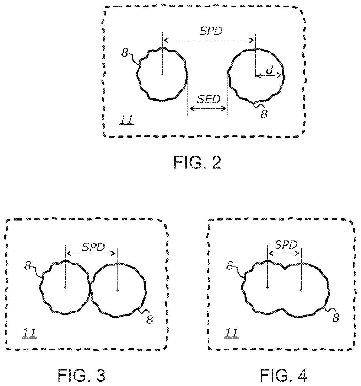
[0175]The term “surface coverage” may be defined as the ratio between a cumulative area of light extraction features 8 within a sampling region and the total area of the sampling region. The area of the sampling region should be at least 100 times greater than the average or typical area of individual light extraction features 8. According to one...

example 2

[0238]A wide-area light guide illumination system was made using an edge-lit planar acrylic light guide having a thickness of about 1.5 mm and major dimensions of about 600 mm by 600 mm. The light guide was patterned on one side using microdots of a UV-cured white ink. The light guide was illuminated from two opposing edges using two strips of white SMD LEDs positioned in a close proximity to the respective edge surfaces. The total light output of the two bare LED strips (without the light guide) was measured at 4,500 lumens.

[0239]The dimensions of the light emitting aperture of each LED were about 1.2 mm by 1.2 mm. The light extraction pattern was produced by a randomized two-dimensional array of microdots deposited to the light guide surface using a commercial flatbed UV printing machine (a UV printer). The density of the pattern was made gradually increasing from the light input edges towards the center of the light guide. Each light extraction feature was represented by an indiv...

example 3

[0244]The wide-area light guide illumination system described the Example 2 was modified by adding an opaque diffuse reflector to the top surface of the planar light guide and measured using the same procedure. The measurement results are summarized in the annotated polar luminous intensity distribution graph shown in FIG. 23. Referring to FIG. 23, the total light output from the bottom surface approximately doubled compared to the Example 2. Furthermore, the measured emission in both orthogonal planes became even more closely resembling the “ideal” Lambertian emission normalized to the same total light output. The deviation between the measured intensity and the calculated intensity based on the Lambertian law constituted 5% or less for most measured angles. Due to the high opacity of the top reflector (˜100%), virtually no light was emitted from the top surface of the device.


PUM

PropertyMeasurementUnit
thicknessaaaaaaaaaa
thicknessaaaaaaaaaa
sizeaaaaaaaaaa

Abstract

Wide-area solid-state illumination devices and systems employing a thin and flexible sheet of an optically transmissive material having at least one broad-area surface patterned with light scattering surface microstructures such as microdots of a non-absorbing UV curable ink. Light is input into the thin and flexible sheet using a number of compact solid-state light sources, such as LEDs, optically coupled to one or more edges or to one or two of the broad-area surfaces defining the thin and flexible sheet. Each surface microstructure forms a semi-opaque layer that extracts light from the thin and flexible sheet and causes light emission from both opposing broad-area surfaces of the sheet.

Description

CROSS-REFERENCE TO RELATED APPLICATIONS[0001]This application also claims priority from U.S. provisional application Ser. No. 62 / 556,415 filed on Sep. 9, 2017, incorporated herein by reference in its entirety.STATEMENT REGARDING FEDERALLY SPONSORED RESEARCH OR DEVELOPMENT[0002]Not ApplicableINCORPORATION-BY-REFERENCE OF MATERIAL SUBMITTED ON A COMPACT DISC[0003]Not ApplicableNOTICE OF MATERIAL SUBJECT TO COPYRIGHT PROTECTION[0004]A portion of the material in this patent document is subject to copyright protection under the copyright laws of the United States and of other countries. The owner of the copyright rights has no objection to the facsimile reproduction by anyone of the patent document or the patent disclosure, as it appears in the United States Patent and Trademark Office publicly available file or records, but otherwise reserves all copyright rights whatsoever. The copyright owner does not hereby waive any of its rights to have this patent document maintained in secrecy, i...

Claims


Application Information

Patent Timeline
Patent Type & Authority Patents(United States)
IPC IPC(8): F21V8/00
CPCG02B6/0061G02B6/0043G02B6/0065G02B6/0076G02B6/0063G02B6/0036
Inventor VASYLYEV, SERGIYMASALITIN, MYKOLA
Owner S V V TECH INNOVATIONS
Why Eureka
Try Eureka