Battery pack

a battery pack and battery technology, applied in the field of batteries, can solve the problems of affecting the performance and the expansion of the prismatic secondary battery, so as to avoid damage or fracture of the battery pack

Active Publication Date: 2020-03-17
SANYO ELECTRIC CO LTD
View PDF11 Cites 0 Cited by
  • Summary
  • Abstract
  • Description
  • Claims
  • Application Information

AI Technical Summary

Benefits of technology

[0022]The embodiments of the present invention can avoid a damage or fracture of a battery pack which may be caused by expansion of prismatic secondary batteries.

Problems solved by technology

Expansion of the wound electrode body causes the wound electrode body to press the battery case outward, which results in expansion of the prismatic secondary battery.
When the force (reaction force) applied to press other components increases excessively due to expansion of the prismatic secondary battery, components of the battery pack, such as binding bars and end plates, may be damaged or fractured.
In addition, expansion of the prismatic secondary battery may degrade performance of the prismatic secondary battery.

Method used


Image

  • Battery pack
  • Battery pack
  • Battery pack

Examples


modification 1

[0108]In the prismatic secondary battery 20 according to the embodiment described above, the sealing plate 2-side end of the positive electrode-joined portion 90 is located at the same position as the sealing plate 2-side end of the negative electrode-joined portion 91, and the bottom 1a-side end of the positive electrode-joined portion 90 is located at the same position as the bottom 1a-side end of the negative electrode-joined portion 91 in the direction perpendicular to the bottom 1a of the prismatic outer body 1. In a prismatic secondary battery according to Modification 1, the positive electrode-joined portion 90 is not located at the same position as the negative electrode-joined portion 91 in the direction perpendicular to the bottom 1a of the prismatic outer body 1. The prismatic secondary battery according to Modification 1 has the same structure as the prismatic secondary battery 20 according to the embodiment except for the positions of the positive electrode-joined porti...

modification 2

[0117]FIG. 14 illustrates the surface of a flat wound electrode body 3 of a prismatic secondary battery according to Modification 2 in which a positive electrode current collector 6 and a negative electrode current collector 8 are connected to the surface. The prismatic secondary battery according to Modification 2 has the same structure as the prismatic secondary battery according to Modification 1.

[0118]As illustrated in FIG. 14, the width of a flat portion 3b of a power generation part 3a of the flat wound electrode body 3 in the direction in which the winding axis of the flat wound electrode body 3 extends (horizontal direction in FIG. 14) is denoted by W1. In the direction in which the winding axis extends, a region between a position 0.25×W1 distant from the center line of the flat portion 3b to one side and a position 0.25×W1 distant from the center line of the power generation part 3a to the other side is defined as a fifth region. When viewed in the direction perpendicular ...


PUM

PropertyMeasurementUnit
thicknessaaaaaaaaaa
packing densityaaaaaaaaaa
thicknessaaaaaaaaaa

Abstract

A battery pack includes a plurality of prismatic secondary batteries with spacers each interposed therebetween. The prismatic secondary batteries each include a flat wound electrode body that is formed by winding a positive electrode plate and a negative electrode plate with a separator interposed therebetween; a prismatic outer body that houses the wound electrode body; and a sealing plate that seals an opening of the flat wound electrode body. The wound electrode body has a wound positive electrode core-exposed portion at one end portion and a wound negative electrode core-exposed portion at the other end portion. A positive electrode current collector is joined to the positive electrode core-exposed portion to form a positive electrode-joined portion, and a negative electrode current collector is joined to the negative electrode core-exposed portion to form a negative electrode-joined portion.

Description

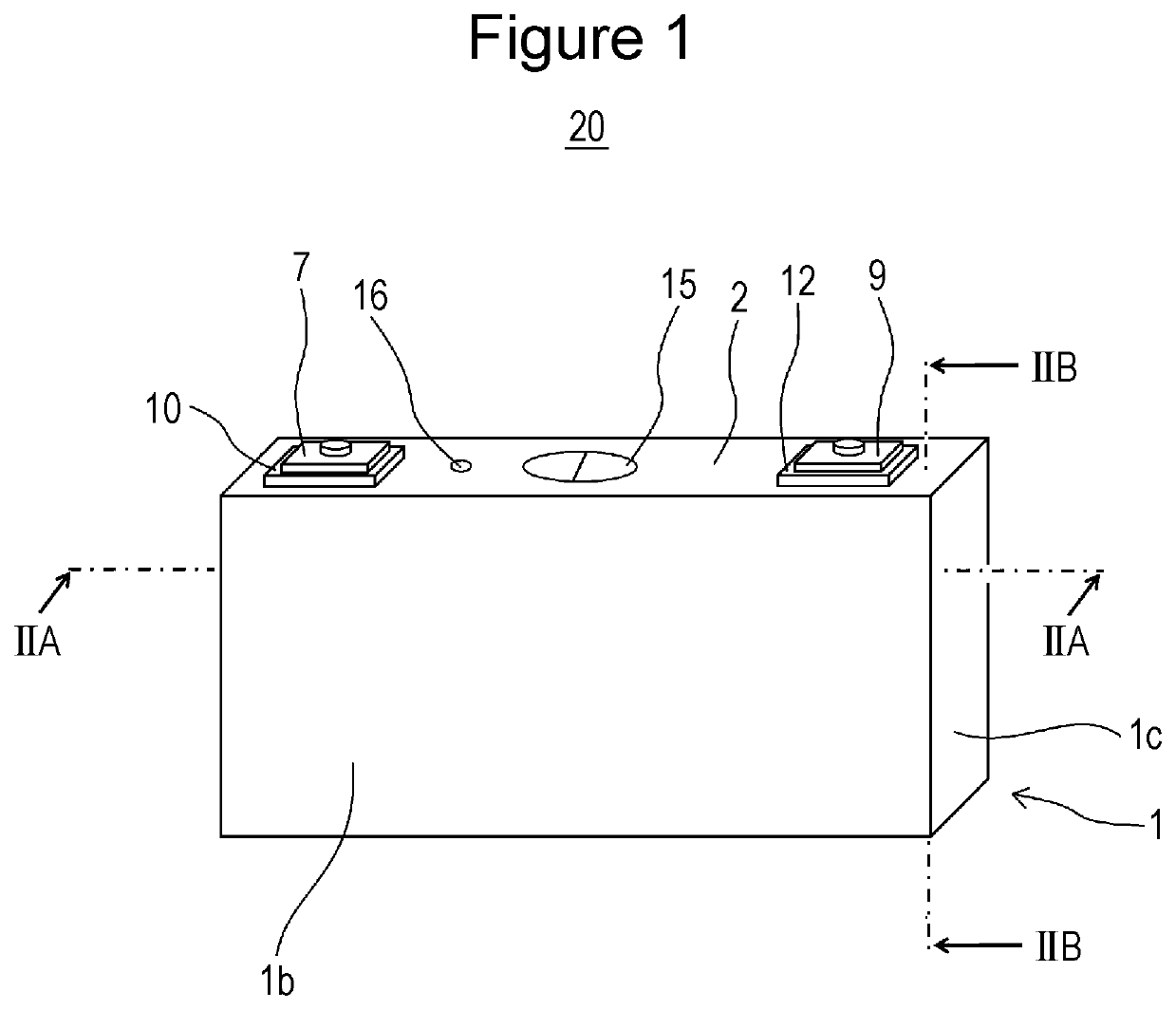
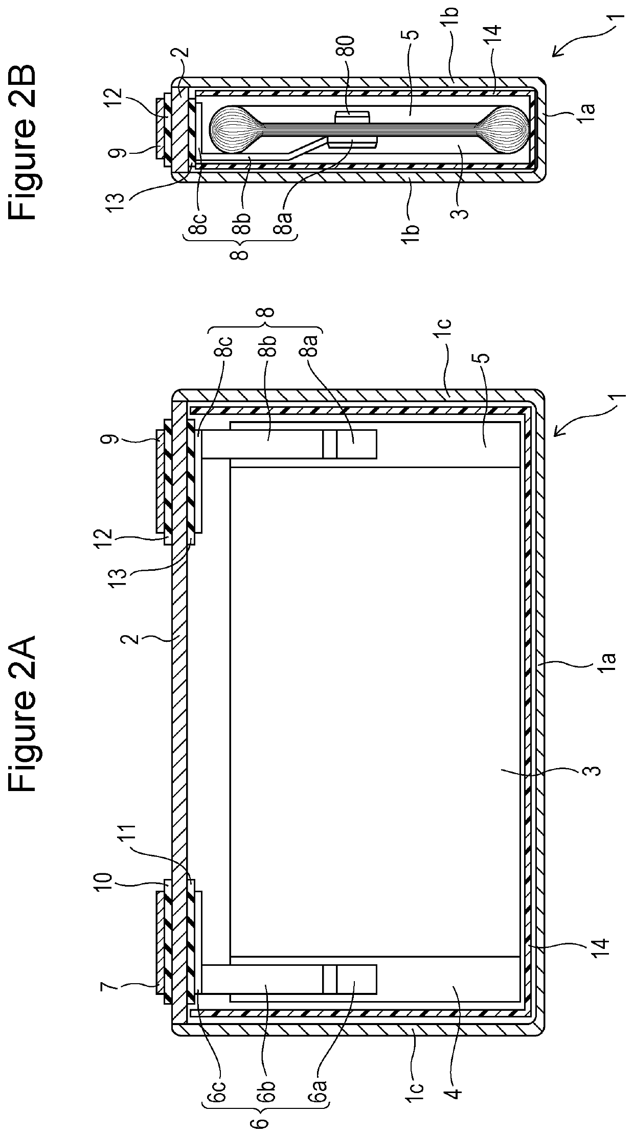
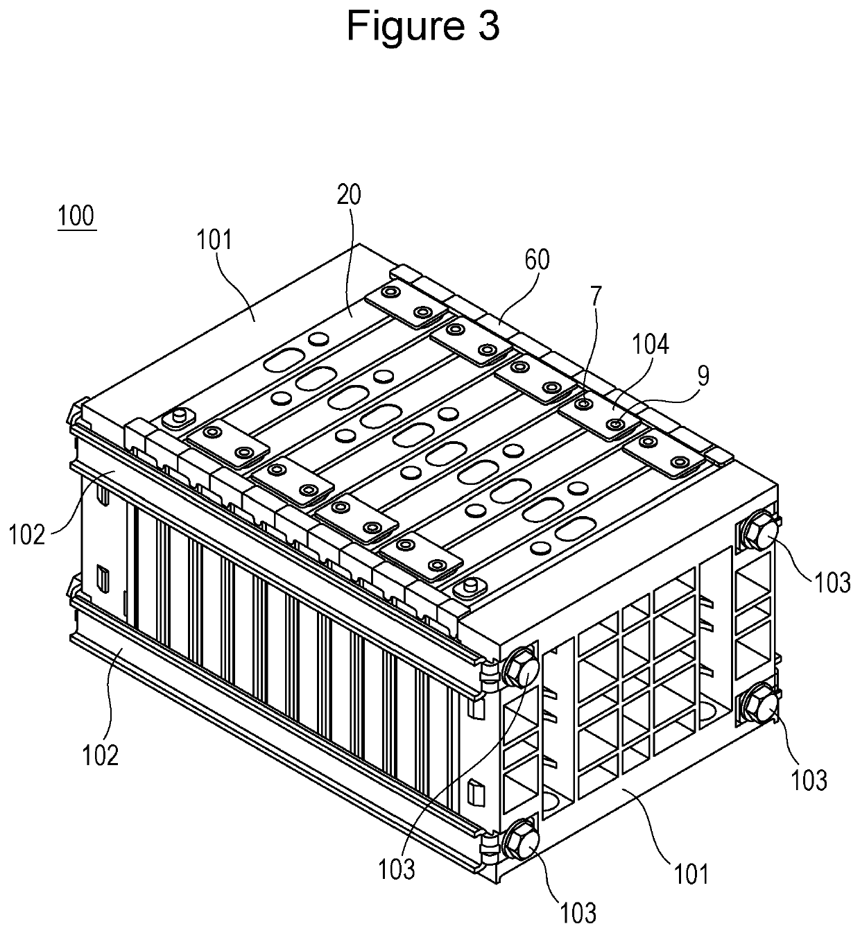
CROSS REFERENCE TO RELATED APPLICATIONS[0001]The present invention application claims priority to Japanese Patent Application No. 2017-052757 filed in the Japan Patent Office on Mar. 17, 2017, the entire contents of which are incorporated herein by reference.BACKGROUND OF THE INVENTIONField of the Invention[0002]The present invention relates to a battery pack including plural prismatic secondary batteries.Description of Related Art[0003]Battery packs including plural prismatic secondary batteries connected in series or parallel are used as driving power sources in, for example, electric vehicles (EVs) and hybrid electric vehicles (HEVs, PHEVs).[0004]In such a battery pack, plural prismatic secondary batteries are arranged such that the wide side surfaces of adjacent prismatic secondary batteries oppose each other with spacers or the like each interposed therebetween. For example, plural prismatic secondary batteries are placed between a pair of end plates, and the pair of end plates...

Claims


Application Information

Patent Timeline
Patent Type & Authority Patents(United States)
IPC IPC(8): H01M2/14H01M2/10H01M10/0587H01M2/02H01M50/209H01M50/293
CPCH01M2/0217H01M2/1077H01M2/14H01M10/0587H01M2220/20H01M2/1094H01M10/0431H01M2200/00H01M50/209H01M50/293Y02E60/10H01M50/103H01M50/24Y02P70/50
Inventor OKADO, TETSUYAMINAMI, KEISUKEMURAOKA, MASASHIARAI, TOMOHARUFUJIHARA, TOYOKI
Owner SANYO ELECTRIC CO LTD
Why Eureka
Try Eureka