A Bolt Looseness Sensing Device Based on Piezoelectric Traction Effect

A bolt loosening and traction effect technology is applied in the direction of using electric/magnetic devices to transmit sensing components, measuring devices, and testing of mechanical components. It can solve the problems of complex monitoring technology design, low sensitivity and high cost, and avoid loosening. Or damage and fracture, low cost, convenient and quick installation and use

Active Publication Date: 2022-07-01
HARBIN INST OF TECH
View PDF13 Cites 0 Cited by
  • Summary
  • Abstract
  • Description
  • Claims
  • Application Information

AI Technical Summary

Problems solved by technology

[0004] In order to solve the problems of complex design, high energy consumption, high cost and low sensitivity of the existing monitoring technology, the present invention provides a bolt looseness sensing device based on piezoelectric traction effect

Method used


Image

  • A Bolt Looseness Sensing Device Based on Piezoelectric Traction Effect
  • A Bolt Looseness Sensing Device Based on Piezoelectric Traction Effect
  • A Bolt Looseness Sensing Device Based on Piezoelectric Traction Effect

Examples


specific Embodiment approach 1

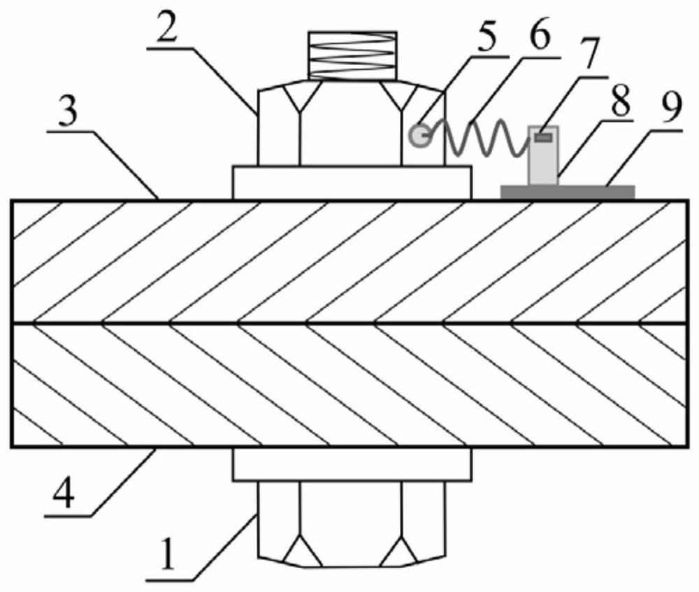
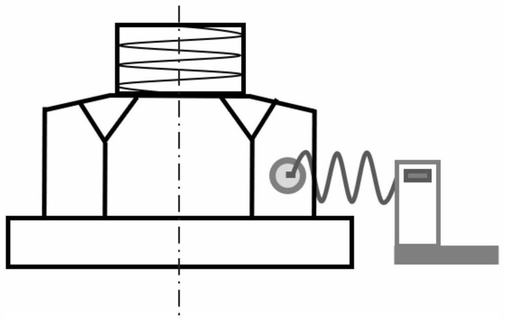
[0022] Specific embodiment one: the following combination Figure 1 to Figure 3 , Figure 5 and Image 6 Illustrating this embodiment, a bolt loosening sensing device with piezoelectric traction effect described in this embodiment includes a connecting end piece 5, a spring 6, a piezoelectric piece 7, a metal elastic piece 8, a bottom bracket 9 and a signal processing module;

[0023] The bottom bracket 9 is embedded with a signal processing module. The upper end surface of the bottom bracket 9 is vertically arranged with a metal dome 8. The piezoelectric plate 7 is attached to the upper end of the metal dome 8. The suspended end of the metal dome 8 is connected to the tail end of the spring 6. The head end is fixedly provided with a connecting end piece 5, and the connecting end piece 5 is pressed on the side of the nut;

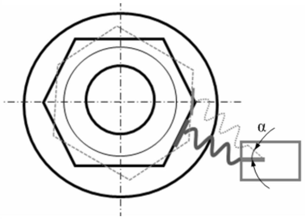
[0024] When the bolt is loosened, the connecting end piece 5 swings with the nut, the connecting end piece 5 drives the spring 6 to expand and contract, ...

specific Embodiment approach 2

[0030] Specific embodiment two: the following combination Figure 4 Describing this embodiment, the difference between this embodiment and the first embodiment is that the head end of the spring 6 connected to the connecting end piece 5 is an equidistant helical structure, preferably an integrally formed connection. The equidistant helical structure of the spring has an excellent stable structure and a large contact surface, making the connection more reliable.

[0031] The end of the conventional spring is a single circle, and there are often protruding ends at the truncation, which is not conducive to the connection with the connecting end piece 5 and the smoothness of the pressing on the nut.

[0032] In this embodiment, the head end of the spring 6 is changed to an equidistant helical structure in order to increase the contact area with the connecting end piece 5, so that the force transmitted by the spring 6 can be more smoothly and positively supported on the nut 2 throu...


PUM


Abstract

A bolt loosening sensing device based on piezoelectric traction effect belongs to the field of mechanical fastener monitoring. The invention solves the problems of complex design, high energy consumption, high cost and low sensitivity of the existing monitoring technology. The device of the invention comprises a connecting end piece, a spring, a piezoelectric piece, a metal shrapnel, a bottom bracket and a signal processing module; the signal processing module is embedded in the bottom bracket, the metal shrapnel is vertically arranged on the upper end surface of the bottom bracket, and the piezoelectric piece is attached to the metal shrapnel The upper end of the metal shrapnel is connected to the tail end of the spring, the head end of the spring is fixed with a connecting end piece, and the connecting end piece is pressed on the side of the nut; when the bolt is loose, the connecting end piece swings with the nut, and the connecting end piece drives the The spring expands and contracts, and the traction force generated by the spring expansion applies a load to the metal shrapnel attached to the piezoelectric sheet to make it bend, and the bending deformation induces the piezoelectric sheet to generate a piezoelectric signal, and the signal processing module receives the piezoelectric signal to realize the perception of bolt loosening.

Description

technical field [0001] The invention relates to a device for monitoring bolt loosening, belonging to the field of mechanical fastener monitoring. Background technique [0002] As one of the most common connection methods, bolted connections are widely used in various fields of national production, such as various constructions, railways, wind power generation, machinery, instruments and aerospace devices, providing great advantages for the connection and assembly of devices and components. convenient. Under normal circumstances, there are two main reasons for the failure of bolts: fracture and loosening, among which loosening is the most common problem. While loose bolts are common and often overlooked, small problems can often lead to major disasters. The tightening state of the bolts will affect the working performance of the equipment, such as abnormal vibration of the equipment, damage to components, etc., and cause casualties and huge economic losses of the enterprise...

Claims


Application Information

Patent Timeline
Patent Type & Authority Patents(China)
IPC IPC(8): G01M13/00G01D5/14
CPCG01M13/00G01D5/14
Inventor 潘振路晓艳
Owner HARBIN INST OF TECH
Why Eureka
Try Eureka