Mechanical arm

A technology of mechanical arms and driving motors, applied in the direction of manipulators, chucks, manufacturing tools, etc., can solve the problems of small clamping force and complex structure, and achieve large clamping force, fast clamping or loosening, and ingenious design Effect

Inactive Publication Date: 2019-10-18
钱海燕
View PDF6 Cites 0 Cited by
  • Summary
  • Abstract
  • Description
  • Claims
  • Application Information

AI Technical Summary

Problems solved by technology

[0004] The problem to be solved by the present invention is to provide a mechanical arm to overcome the defects of complex structure and small clamping force in the prior art

Method used


Image

  • Mechanical arm
  • Mechanical arm
  • Mechanical arm

Examples


Embodiment Construction

[0015] The specific embodiments of the present invention will be described in further detail below with reference to the accompanying drawings and embodiments. The following examples are intended to illustrate the present invention, but not to limit the scope of the present invention.

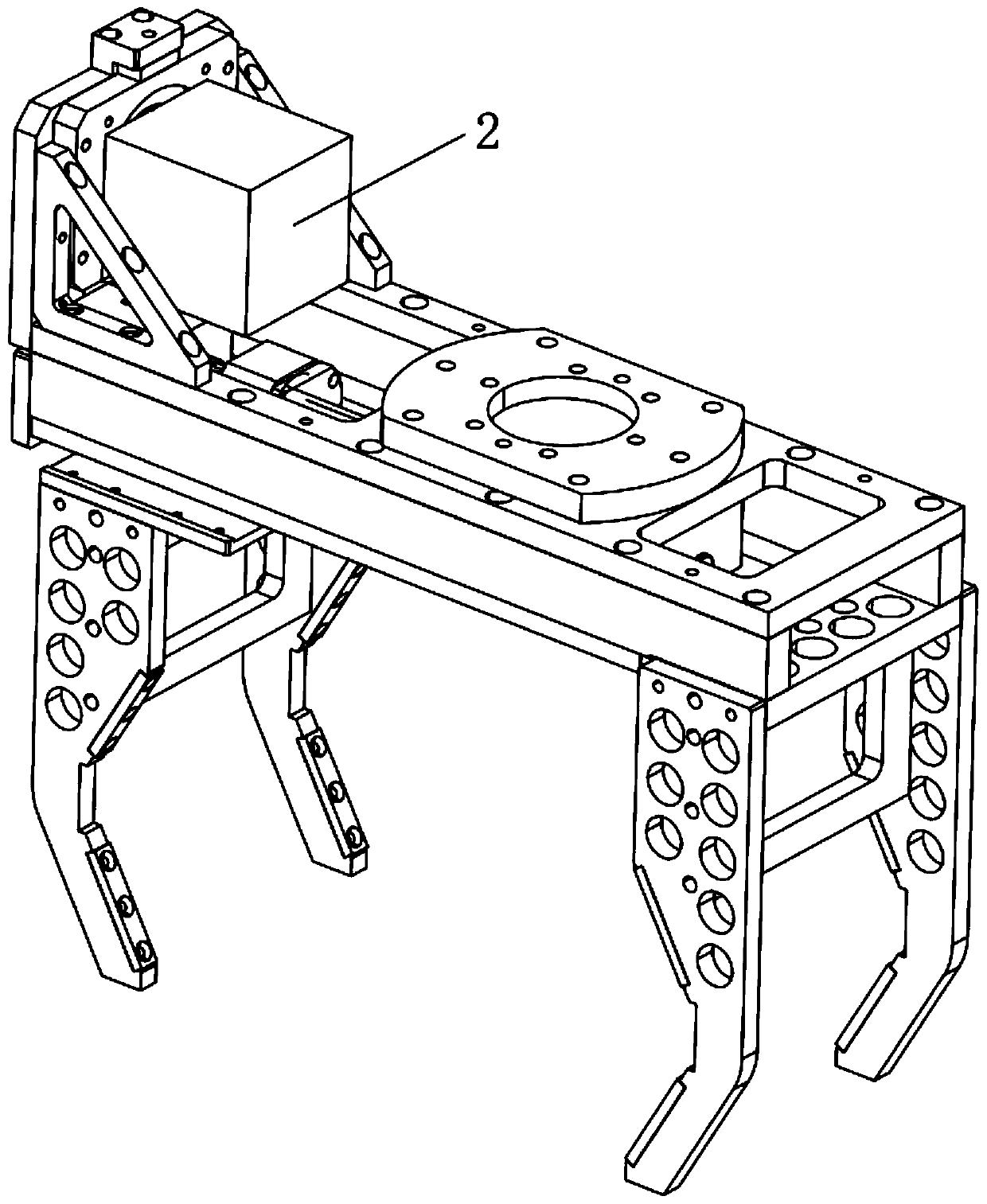
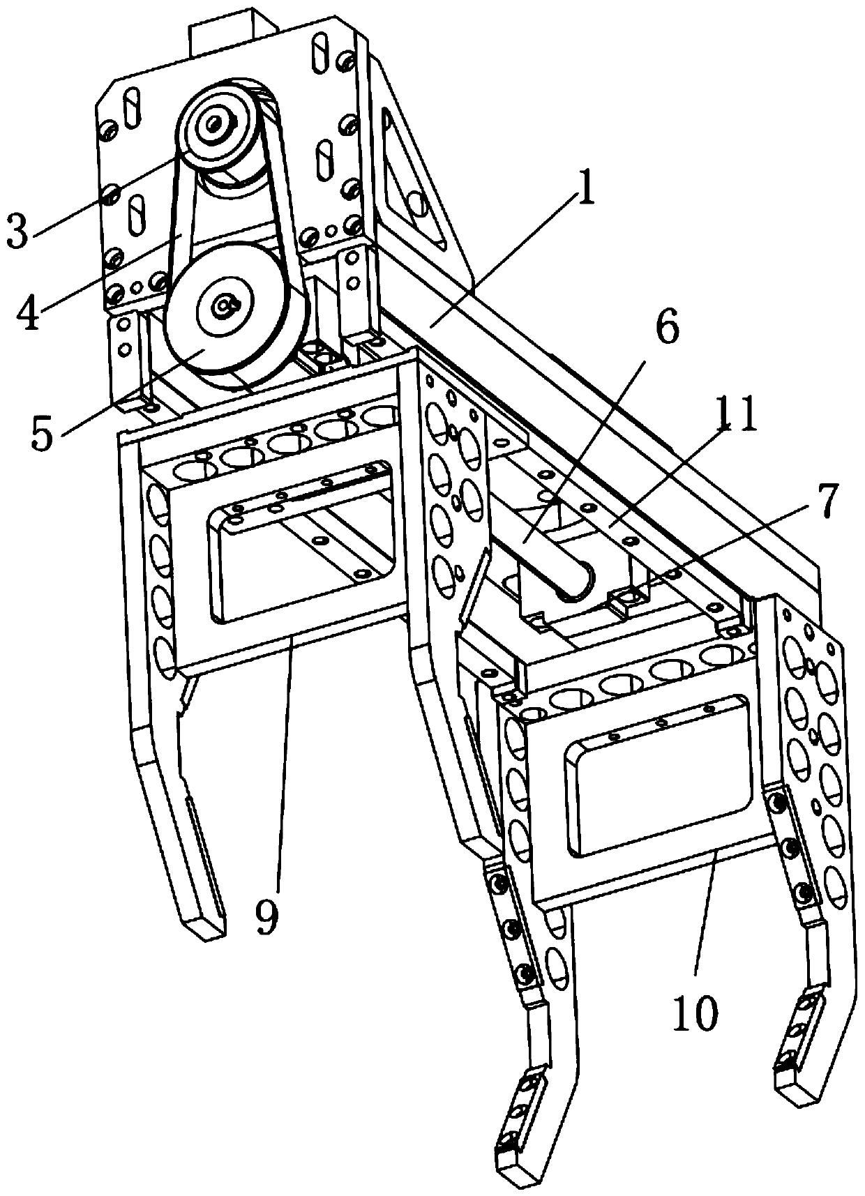
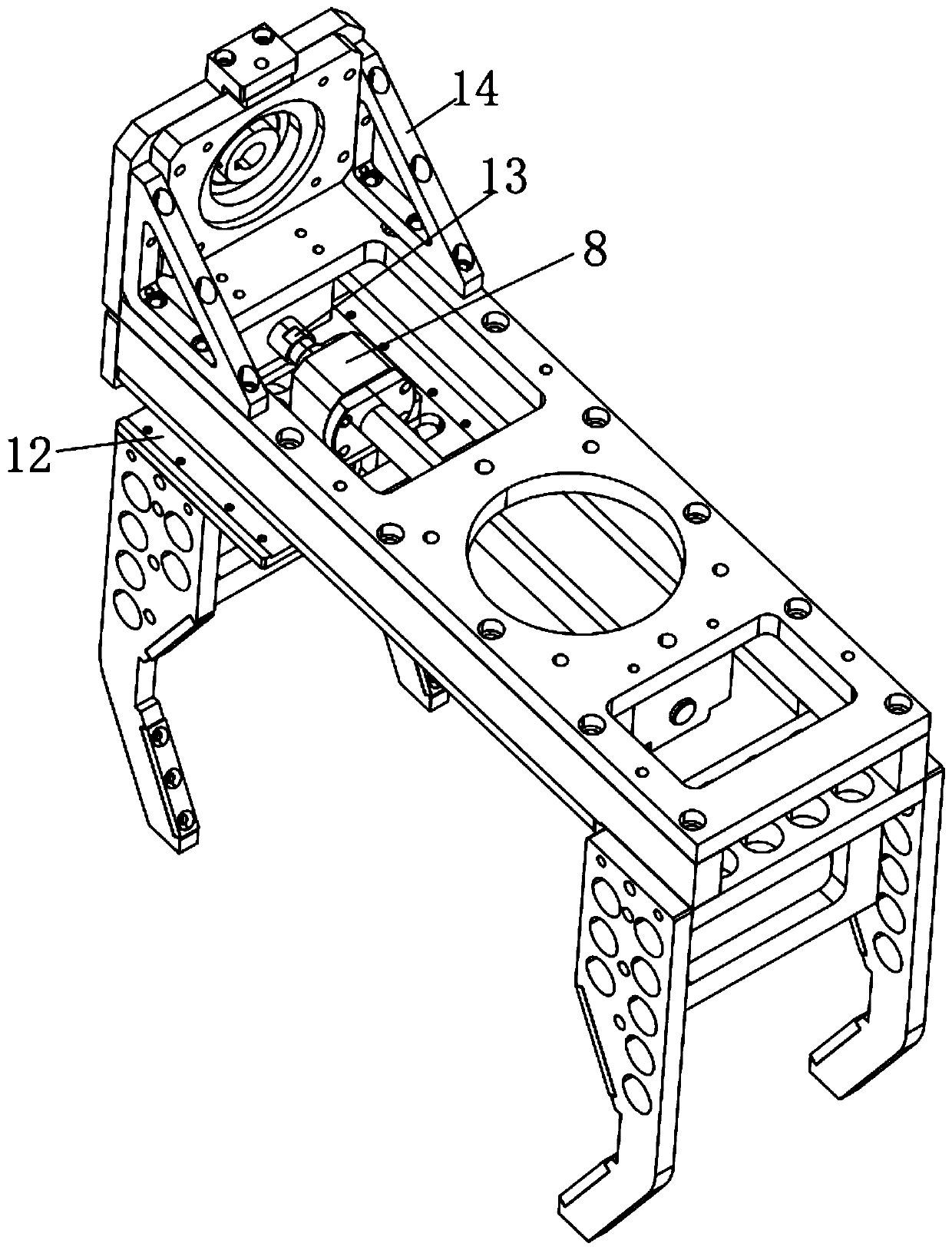
[0016] like Figure 1 to Figure 3 As shown, a mechanical arm of the present invention includes a main body base 1, a drive motor 2, a first pulley 3, a belt 4, a second pulley 5, a screw 6, a screw seat 7, a screw nut 8, a moving clip 9, a fixed Clamp 10, guide rail 11 and slider 12; the drive motor 2 is fixedly installed on the upper end side of the main body base 1; the rotating shaft of the drive motor 2 is fixed and rotated synchronously with the first pulley 3; the second The pulley 5 and the screw 6 are fixed to achieve synchronous rotation, the other end of the screw 6 is rotatably connected with the screw base 7, and the screw base 7 is fixedly installed on the other side of the lower ...


PUM


Abstract

The invention provides a mechanical arm. The mechanical arm comprises a main seat, a driving motor, a first belt pulley, a belt, a second belt pulley, a screw, a screw seat, a screw rod nut, a movingclamp, a fixing clamp, a guide rail and a sliding block, wherein the driving motor is fixedly arranged on one side of the upper end of the main body seat, a rotating shaft of the driving motor is fixedly and synchronously rotated with the first belt wheel, the second belt wheel and the screw rod are fixed to realize synchronous rotation, the other end of the screw rod is rotationally connected with the screw rod base, the screw seat is fixedly arranged on the other side of the lower end of the main body seat, the lower end of the screw rod nut is fixed with the movable clamp, the screw rod isin threaded connection with the screw rod nut, the two sides of the upper end of the moving clamp are provided with the sliding blocks, and the two sides of the lower end of the main body seat are provided with the guide rails which are in sliding fit with the sliding blocks. The design is ingenious, the object can be quickly clamped or loosened, the operation is convenient, and the clamping forceis large.

Description

technical field [0001] The invention relates to the technical field of mechanical equipment, in particular to a mechanical arm. Background technique [0002] It is an automatic operation device that can imitate some action functions of human hands and arms to grab, carry objects or operate tools according to a fixed program. The manipulator is the earliest industrial robot and the earliest modern robot. It can replace the heavy labor of humans to realize the mechanization and automation of production, and can operate in harmful environments to protect personal safety. Therefore, it is widely used in machinery manufacturing, metallurgy, Electronics, light industry and atomic energy sectors. However, the existing mechanical arm has a complex structure and small clamping force. SUMMARY OF THE INVENTION [0003] technical problem to be solved [0004] The problem to be solved by the present invention is to provide a mechanical arm to overcome the defects of complex structur...

Claims


Application Information

Patent Timeline
Patent Type & Authority Applications(China)
IPC IPC(8): B25J15/00
CPCB25J15/00
Inventor 钱海燕
Owner 钱海燕
Why Eureka
Try Eureka