Card edge connector structure

a connector and card edge technology, applied in the direction of coupling device connection, coupling protective earth/shielding arrangement, instruments, etc., can solve the problems of complicated assembly of internal components of the card edge connector, and achieve the effects of saving labor and cost, increasing assembly convenience, and increasing grounding efficiency

Active Publication Date: 2020-03-24
JESS-LINK PRODUCTS
View PDF7 Cites 3 Cited by
  • Summary
  • Abstract
  • Description
  • Claims
  • Application Information

AI Technical Summary

Benefits of technology

[0004]The present invention is to provide a card edge connector structure, in which a grounding plate is disposed between two electrical conductive terminal sets and extended with a plurality of grounding elastic arms, each of the ground elastic arms is elastically abutted against an inner side of each of the grounding terminals, thereby increasing the grounding efficiency of the card edge connector structure and providing the assembly convenience.
[0006]Based on what has been disclosed above, there is only one grounding plate required to enable the grounding terminals at the left side and the right side to be grounded, so that the card edge connector structure is provided with advantages of increasing the grounding efficiency, saving labor and cost and increasing the assembly convenience.
[0007]Based on what has been disclosed above, a middle partition plate in the insulation main body is extended with plural fasten columns and has two latch slots, the grounding plate has plural penetrated holes, each of the fasten columns of the middle partition plate is inserted in each of the penetrated holes, and a front side and a rear side of the grounding plate are upwardly bent and extended for forming two bending protruding parts, each of the bending protruding parts is latched in each of the latch slots of the middle partition plate, so that the grounding plate can be rapidly and easily fastened below the middle partition plate, thereby greatly lowering the assembly cost of the grounding plate and allowing a problem of the location of the grounding plate being displaced to be avoided.

Problems solved by technology

However, the above-mentioned interface card is required to be electrically connected to a card edge connector, but the assembly of internal components of the card edge connector is complicated, especially different connecting means for connecting terminals and a grounding plate are provided by various providers.

Method used


Image

  • Card edge connector structure
  • Card edge connector structure
  • Card edge connector structure

Examples


Embodiment Construction

[0015]A preferred embodiment of the present invention will be described with reference to the drawings.

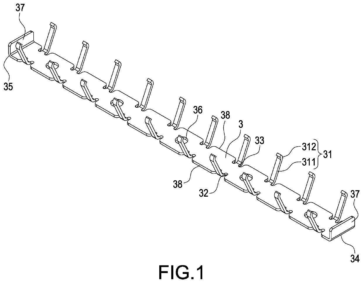
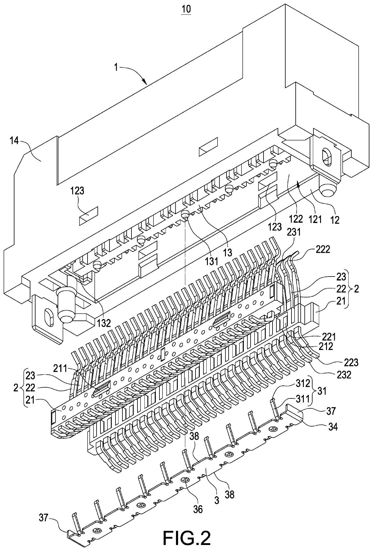
[0016]Please refer from FIG. 1 to FIG. 7, the present invention provides a card edge connector structure 10 mainly including an insulation main body 1, two electrical conductive terminal sets 2 and a grounding plate 3.

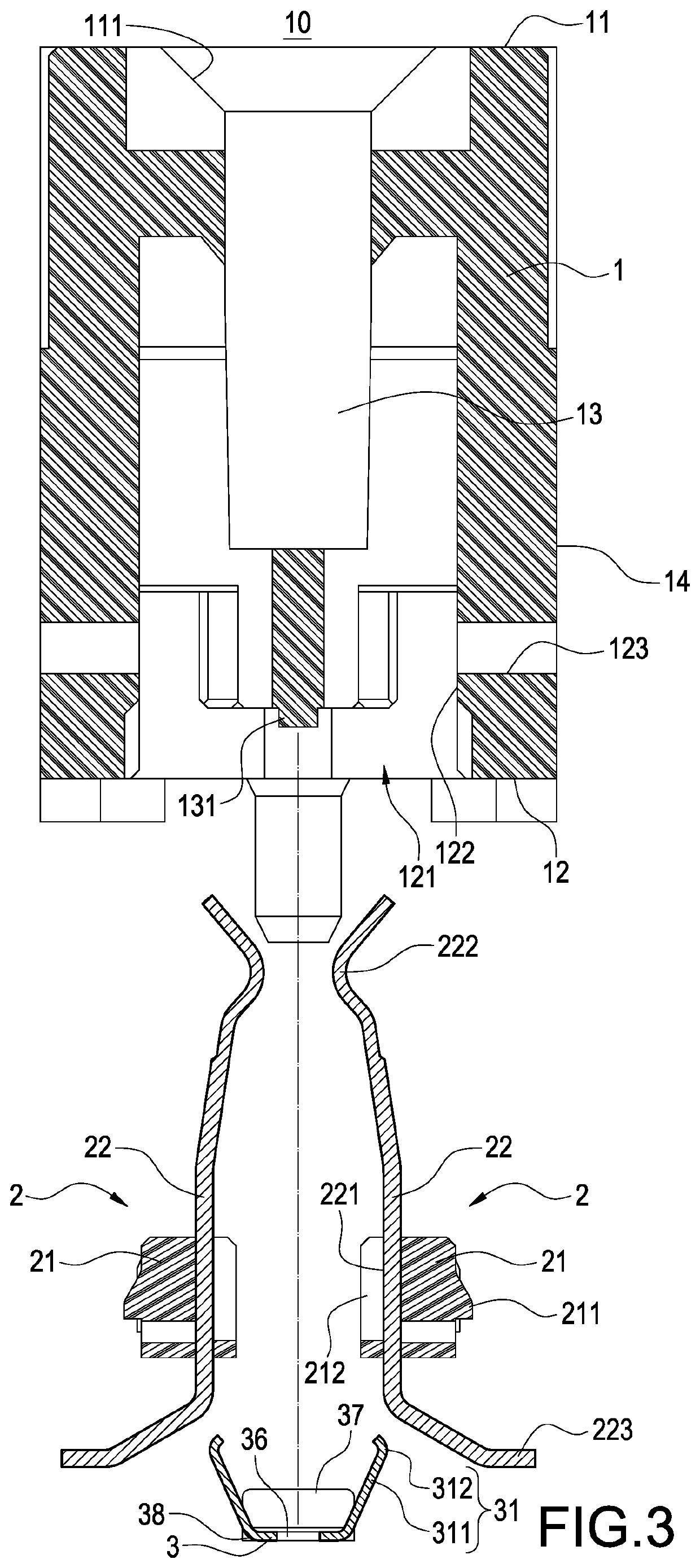
[0017]As shown from FIG. 2, FIG. 3, FIG. 4, FIG. 6 and FIG. 7, an insertion surface 11 is disposed at one side of the insulation main body 1 and an installation surface 12 is disposed at another side thereof. The insertion surface 11 has an insertion port 111, a penetrated port 121 communicated with the insertion port 111 is inwardly disposed on the installation surface 12 of the insulation main body 1, and the insulation main body 1 has an inner wall 122 inside the penetrated port 121.

[0018]Moreover, a middle partition plate 13 is disposed at an inner side of the insulation main body 1 and an outer surround wall 14 is disposed at an outer side thereof. The middle par...


PUM


Abstract

A card edge connector structure includes: an insulation main body, having one side disposed with an insertion surface and having another side disposed with an installation surface; the insertion surface has an insertion port; two electrical conductive terminal sets, disposed in the insulation main body with a parallel arrangement means; each electric conductive terminal set has a positioning seat, grounding terminals and electrical conductive terminals protruded from the positioning seat, each grounding terminal has an inner side, a first end exposed in the insertion port and a second end exposed on the installation surface; and a grounding plate, disposed between the two electrical conductive terminal sets; two sides of the grounding plate are extended with grounding elastic arms towards a direction of each first end, and each grounding elastic arm is elastically abutted against the inner side of each grounding terminal.

Description

BACKGROUND OF THE INVENTIONField of the Invention[0001]The present invention relates to a connector structure, especially to a card edge connector structure.Description of Related Art[0002]The electronic devices have been commonly used, and the transmission requirement for a peripheral interface card such as an expansion card or display card is gradually increased, so that the skilled people in the art have developed interface cards with different interface specifications such as a PCI Express, a Mini PCI express, or M. 2 (as known as NGFF), wherein the NGFF interface card is more flexible in the actual use because it has different sizes, and the NGFF interface card is able to support SATA and PCIe interfaces, so that the NGFF interface card has advantages of saving electricity and rapid transmission speed and has become the main specification in the high-end market.[0003]However, the above-mentioned interface card is required to be electrically connected to a card edge connector, b...

Claims


Application Information

Patent Timeline
Patent Type & Authority Patents(United States)
IPC IPC(8): H01R13/652G06F13/40H01R12/72G06F1/18H05K1/11H01R12/73H01R12/70
CPCH01R12/721G06F1/185H01R12/737H05K1/117G06F13/409H01R12/7005H01R2201/06H01R12/716H01R13/6471
Inventor KAO, YA-FENLIU, CHING-HUNGLI, HSU-YUYANG, YUN-CHANG
Owner JESS-LINK PRODUCTS
Why Eureka
Try Eureka