System and method for controlling the orientation of ground engaging elements on an agricultural implement

a technology of engaging elements and agricultural implements, applied in the field of agricultural implements, can solve the problems of difficult reengagement of soil by ground engaging elements, and achieve the effects of reducing biasing force, reducing biasing force, and reducing biasing for

Active Publication Date: 2020-03-31
CNH IND CANADA
View PDF33 Cites 2 Cited by
  • Summary
  • Abstract
  • Description
  • Claims
  • Application Information

AI Technical Summary

Benefits of technology

[0006]In one aspect, the present subject matter is directed to a method for controlling an orientation of ground engaging elements of a harrow of an agricultural implement when adjusting the position of the harrow relative to the ground. The harrow may include a support arm configured to support the ground engaging elements relative to the ground. The method may include controlling, with a computing device, an operation of an actuator coupled to the support arm such that the actuator applies an actuator force against the support arm when the harrow is disposed at an operating position relative to the ground. The actuator force may result in a biasing force being applied on the ground engaging elements that biases the ground engaging elements toward a vertical orientation as the ground engaging elements contact the ground. The method may also include receiving, with the computing device, a first input indicative of an instruction to move the harrow from the operating position to a raised position relative to the ground. Furthermore, after receiving the input, the method may include controlling, with the computing device, the operation of the actuator such that the actuator force applied against the support arm is adjusted in a manner that reduces the biasing force being applied on the ground engaging elements. Additionally, the method may include initiating, with the computing device, movement of the harrow from the operating position to the raised position to raise the ground engaging elements above the ground after reducing the biasing force being applied on the ground engaging elements.
[0007]In another aspect, the present subject matter is directed to a system for controlling an orientation of ground engaging elements of a harrow of an agricultural implement when adjusting the position of the harrow relative to the ground. The system may include a support arm, a plurality of ground engaging elements supported on the support arm, and an actuator coupled to the support arm. A controller of the system may be configured to control an operation of the actuator such that actuator applies an actuator force against the support arm when the harrow is disposed at an operating position relative to the ground. The actuator force may result in a biasing force being applied on the ground engaging elements that biases the ground engaging elements toward a vertical orientation as the ground engaging elements contact the ground. The controller may also be configured to receive a first input indicative of an instruction to move the harrow from the operating position to a raised position relative to the ground. After receiving the first input, the controller may be configured to control the operation of the actuator such that the actuator force applied against the support arm is adjusted in a manner that reduces the biasing force being applied on the ground engaging elements. Furthermore, the controller may be configured to initiate movement of the harrow from the operating position to the raised position to raise the ground engaging elements above the ground after reducing the biasing force being applied on the ground engaging elements.

Problems solved by technology

Such a vertical orientation makes it difficult for the ground engaging elements to reengage the soil when the harrow is lowered back into the operating position.

Method used


Image

  • System and method for controlling the orientation of ground engaging elements on an agricultural implement
  • System and method for controlling the orientation of ground engaging elements on an agricultural implement
  • System and method for controlling the orientation of ground engaging elements on an agricultural implement

Examples


Embodiment Construction

[0018]Reference now will be made in detail to embodiments of the invention, one or more examples of which are illustrated in the drawings. Each example is provided by way of explanation of the invention, not limitation of the invention. In fact, it will be apparent to those skilled in the art that various modifications and variations can be made in the present invention without departing from the scope or spirit of the invention. For instance, features illustrated or described as part of one embodiment can be used with another embodiment to yield a still further embodiment. Thus, it is intended that the present invention covers such modifications and variations as come within the scope of the appended claims and their equivalents.

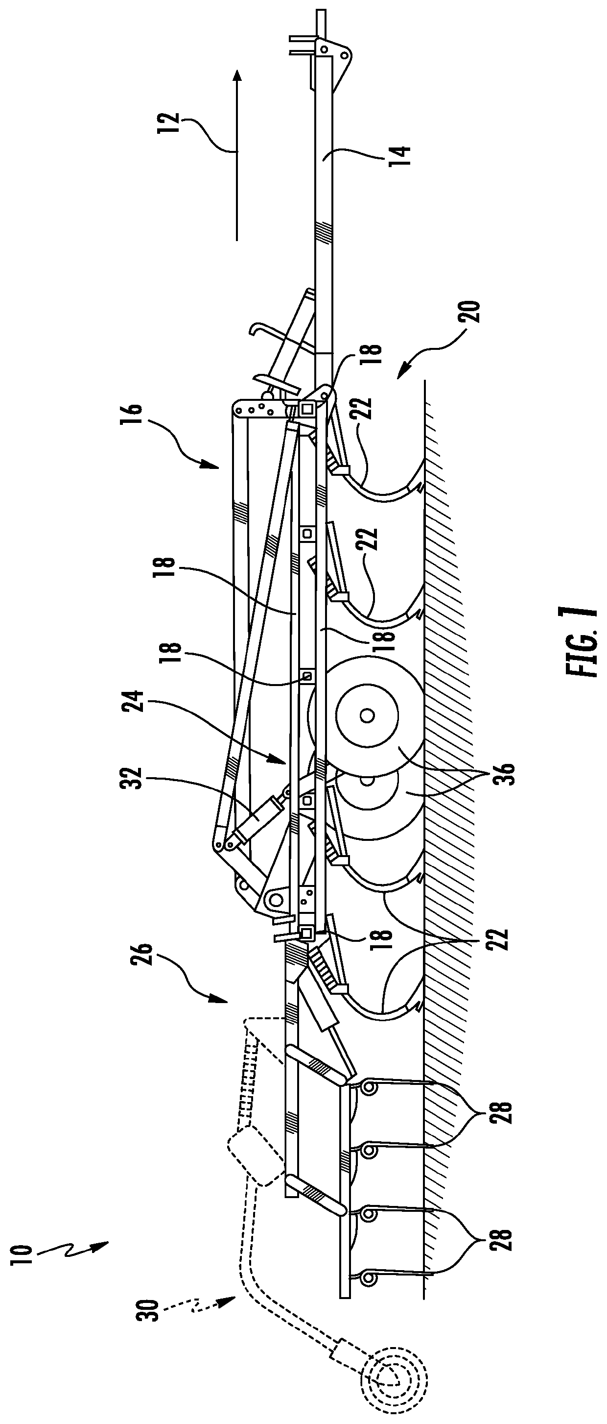
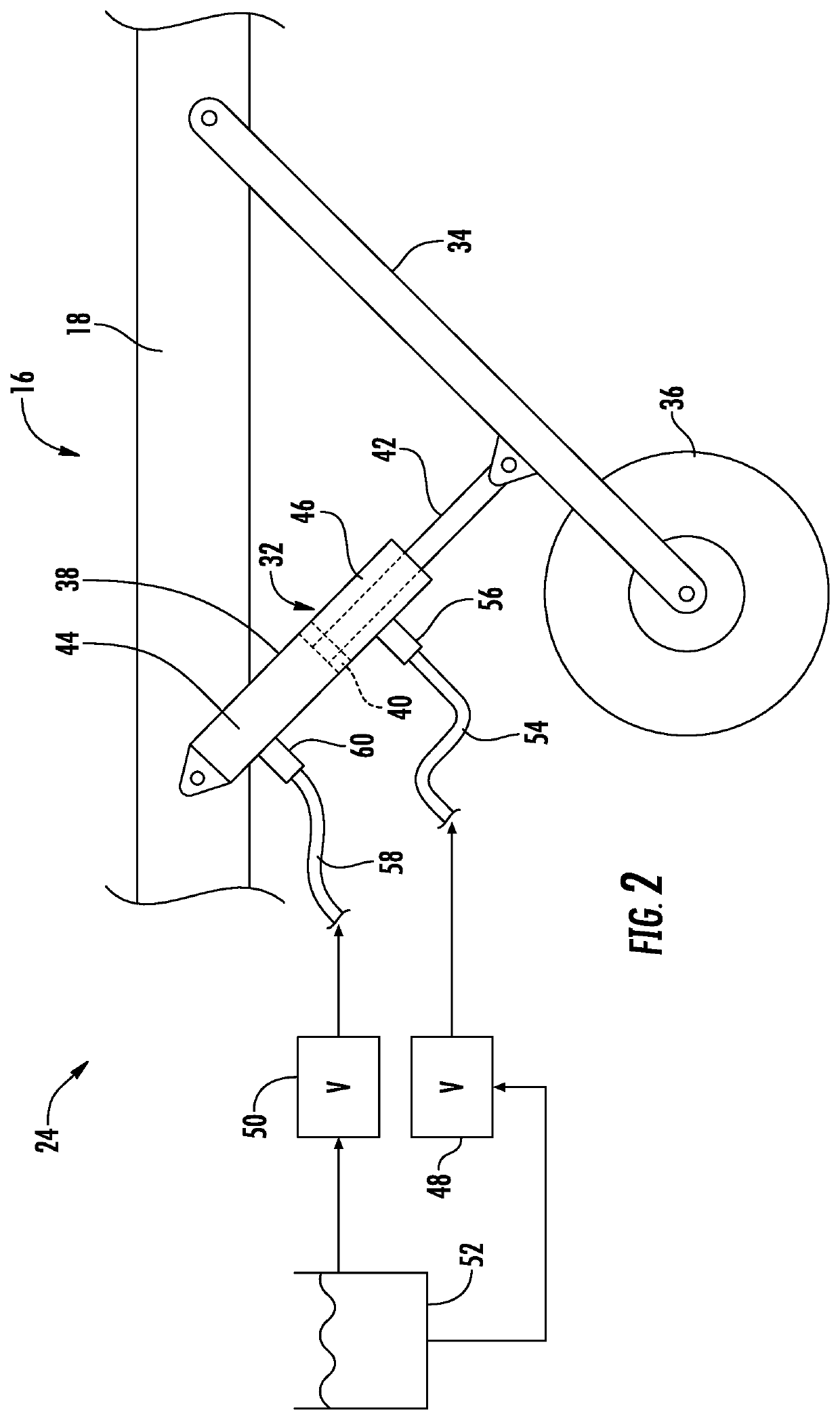
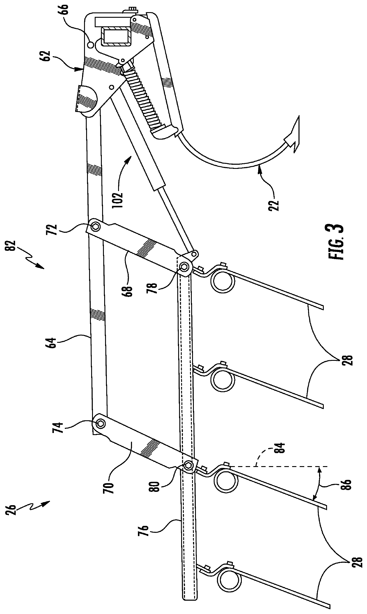
[0019]In general, the present subject matter is directed to systems and methods for controlling the orientation of ground engaging elements of a harrow of an agricultural implement when adjusting the position of the harrow relative to the ground. Specifical...


PUM


Abstract

A method for controlling an orientation of ground engaging elements of a harrow of an agricultural implement may include controlling an operation of an actuator such that the actuator applies an actuator force against a support arm when the harrow is disposed at an operating position. The method may also include receiving an input indicative of an instruction to move the harrow from the operating position to a raised position. Furthermore, after receiving the input, the method may include controlling the operation of the actuator such that the actuator force applied against the support arm is adjusted in a manner that reduces the biasing force being applied on the ground engaging elements. Additionally, the method may include initiating movement of the harrow from the operating position to the raised position to raise the ground engaging elements above the ground after reducing the biasing force.

Description

FIELD[0001]The present disclosure generally relates to agricultural implements and, more particularly, to systems and methods for controlling the orientation of ground engaging elements on a harrow of an agricultural implement when adjusting the position of the harrow relative to the ground.BACKGROUND[0002]A wide variety of agricultural implements may be used to prepare soil for planting. One such implement is a harrow. As is generally known, harrows may be configured to be towed behind a work vehicle, such as tractor, to level soil after it has been tilled by, e.g., a cultivator. Level soil promotes uniform planting depth and uniform germination. More specifically, harrows typically include a plurality of ground engaging elements, such as tines or spikes, which extend downward from a frame of the harrow. These ground engaging elements may be configured to contact and engage the soil. As such, a bias force exerted on the ground engaging elements maintains the contact between ground ...

Claims


Application Information

Patent Timeline
Patent Type & Authority Patents(United States)
IPC IPC(8): A01B63/00A01B63/10A01B73/00A01B21/04A01B49/02A01B63/22A01B21/08
CPCA01B73/00A01B49/027A01B21/08A01B63/22A01B63/008A01B21/04A01B63/10
Inventor HENRY, JAMES W.
Owner CNH IND CANADA
Why Eureka
Try Eureka