
Reel changing device and reel changing method

a reel and reel technology, applied in membrane technology, membranes, transportation and packaging, etc., can solve the problems of inability to keep the fiber strand tensioned, the structure is complex in the technical sense, and the operation is only fully automated, so as to achieve simple and efficient reel change, maintain tension, and facilitate handling

Active Publication Date: 2020-03-31
B BRAUN AVITUM
View PDF17 Cites 0 Cited by
  • Summary
  • Abstract
  • Description
  • Claims
  • Application Information

AI Technical Summary

Benefits of technology

[0007]Against this background, it is an object of the present invention to avoid or at least alleviate the drawbacks of the state of the art. Especially, an object of the present invention consists in providing a reel changing device and a reel changing method which enable easy and efficient handling, especially with respect to a continuous winding of (hollow) fiber strands and with respect to a subsequent removal of wound (hollow) fiber bundles and are suited both for manual and for automated operation.
[0008]Thus, easy and efficient reel change handling for winding hollow fiber strands / bundles is to be provided.

Problems solved by technology

The reel device of WO 2008 / 067934 A2 has the drawback, however, that it has an extremely complicated structure in the technical respect and can only be operated in a fully automated manner.
Furthermore, it is not feasible to keep the fiber strand tensioned when it is transferred from the one beam-type reel to the other beam-type reel so that in addition an upstream thread buffer is required to keep the fiber strand continuously exiting the spinning device tensioned.

Method used


Image

  • Reel changing device and reel changing method
  • Reel changing device and reel changing method

Examples


first embodiment

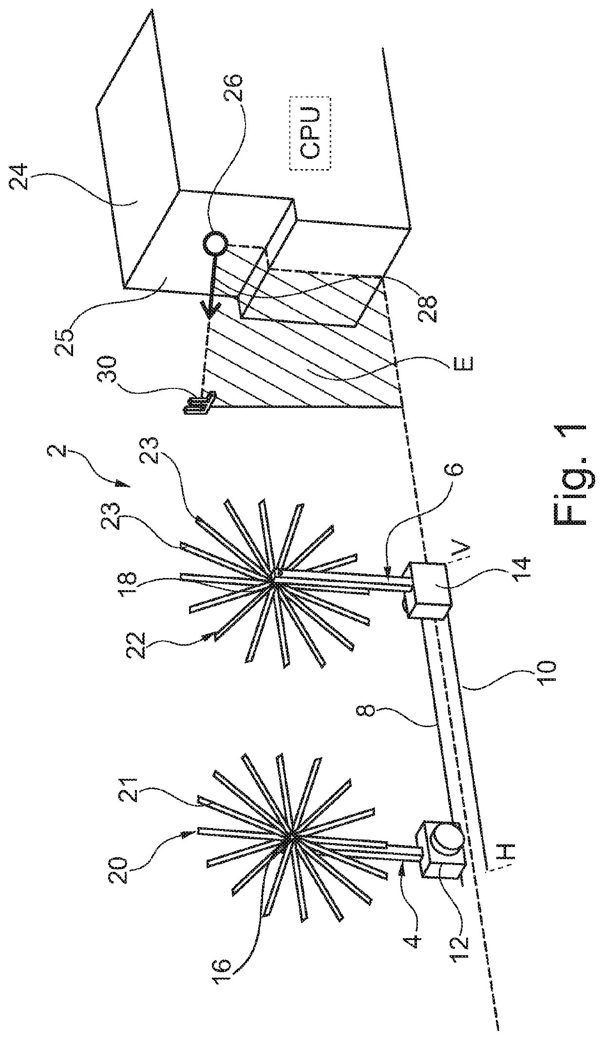
[0040]In FIG. 1, a reel changing device 2 is shown. The reel changing device 2 includes two reel carriers 4, 6, namely a first reel carrier 4 and a second reel carrier 6. The first reel carrier 4 is received and guided in a first linear guide 8. The second reel carrier 6 is received and guided in a second linear guide 10. The linear guides 8, 10 are located on the bottom. The reel carriers 4, 6 extend perpendicularly from the linear guides 8, 10 and thus away from the bottom. In particular, the reel carriers 4, 6 include guide portions 12, 14 via which the reel carriers 4, 6 are guided to be linearly movable in the linear guides 8, 10.

[0041]Each of the reel carriers 4, 6 includes holding portions 16, 18 in the form of retaining bolts. At the holding portion 16 of the first reel carrier 4 a first reel wheel 20 is releasably or replaceably arranged / fastened. At the holding portion 18 of the second reel carrier 6 a second reel wheel 22 is releasably or replaceably arranged / fastened. Ea...

second embodiment

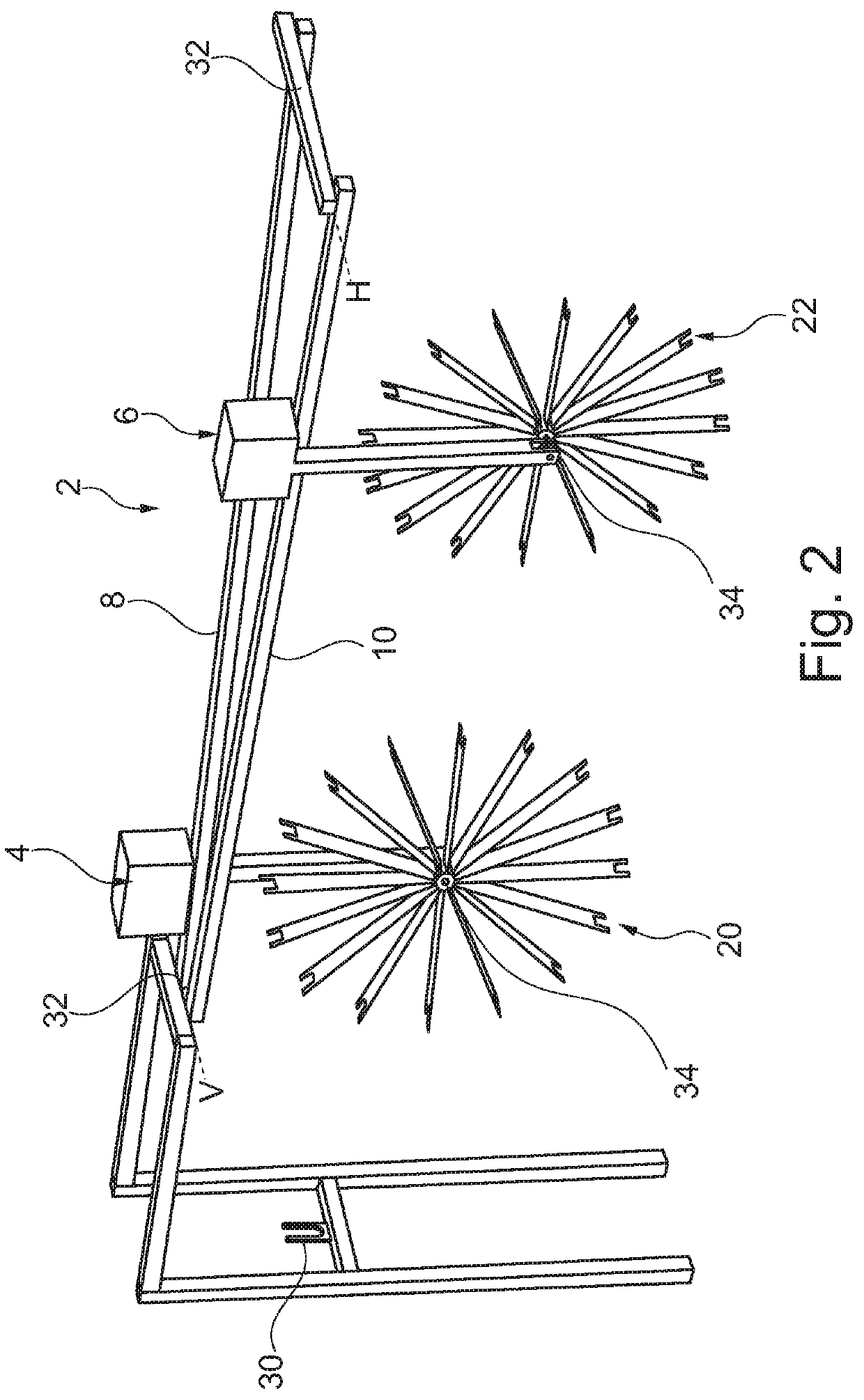
[0049]In the second embodiment, the fiber strand continuously exiting the spinning machine (not shown) is initially supplied to the fiber strand guiding means 30. From there the fiber strand is first placed on and wound onto the first reel wheel 20. As soon as the first reel wheel 20 is completely wound, the fiber strand is manually pinched off and cut off at the reel wheel 20 by a user or operator. Subsequently, the fiber strand is guided manually to the second reel wheel 22 which is close to the rear position H. After that, the fiber strand is placed / put onto the second reel wheel 22. While the second reel wheel 22 now winds up the fiber strand, it is slowly moved toward the front position V, i.e. to the left in FIG. 2. The filled or completely wound-up reel wheel 20 is moved or pushed manually to the rear position H, i.e. to the right in FIG. 2. This is followed by removal of the fiber bundle wound onto the reel wheel 20. This operation is repeated with each change of reel.

[0050]...


PUM

PropertyMeasurementUnit
angleaaaaaaaaaa
torqueaaaaaaaaaa
lengthaaaaaaaaaa

Abstract

A reel changing device is described for reeling fiber bundles from a fiber strand exiting a spinning device, including at least a first reel carrier and a second reel carrier on each of which a reel suited for winding up the fiber strand is arranged and which are movably received and guided in at least a first reel guide and a second reel guide so that the reels are adapted to be positioned one after another in an exit direction of the fiber strand so as to enable, in the case of a reel change, the fiber strand to be directly transferred from the first reel arranged on the first reel carrier to the second reel arranged on the second reel carrier. Moreover, a reel changing method in such reel changing device is described.

Description

CROSS REFERENCE TO RELATED APPLICATIONS[0001]This application claims priority to German application DE 10 2016 115 497.0 filed Aug. 22, 2016, the contents of such application being incorporated by reference herein.FIELD OF THE INVENTION[0002]The present invention relates to a reel changing device provided for reeling / winding a (hollow) fiber strand exiting a spinning device. The invention further relates to a reel changing method for reeling fiber bundles in such reel changing device.BACKGROUND OF THE INVENTION[0003]It is known from the state of the art to use hollow fiber bundles for manufacturing dialysis filters. Dialysis filters are basically employed in various extracorporeal blood treatment processes such as hemodialysis, hemofiltration or hemodiafiltration. For manufacturing dialysis filters, at first a hollow fiber strand continuously exiting a spinning machine / device is wound / reeled onto rotating reels or, respectively, reel wheels. As soon as a rotating reel or a rotating ...

Claims


Application Information

Patent Timeline
Patent Type & Authority Patents(United States)
IPC IPC(8): D01F1/08B65H54/56B01D63/02D01G1/04B65H54/58B65H67/056D01D5/24
CPCD01G1/04D01F1/08D01D5/24B65H67/056B65H54/58B65H54/56B01D63/021B65H2701/33B01D2323/42B65H67/044B01D63/0233
Inventor KÄSTNER, FALK
Owner B BRAUN AVITUM
Learn More