
Method and apparatus for a feed into a gasifier utilizing a slurry

a gasification system and feed technology, applied in the direction of lighting and heating apparatus, combustible gas production, grain treatment, etc., can solve the problems of increasing the amount of drying required to maintain reliable flow, increasing the potential for gasification process effluent emissions, and increasing the potential for dust explosions when stored

Active Publication Date: 2012-05-08
AIR PROD & CHEM INC
View PDF3 Cites 0 Cited by
  • Summary
  • Abstract
  • Description
  • Claims
  • Application Information

AI Technical Summary

Benefits of technology

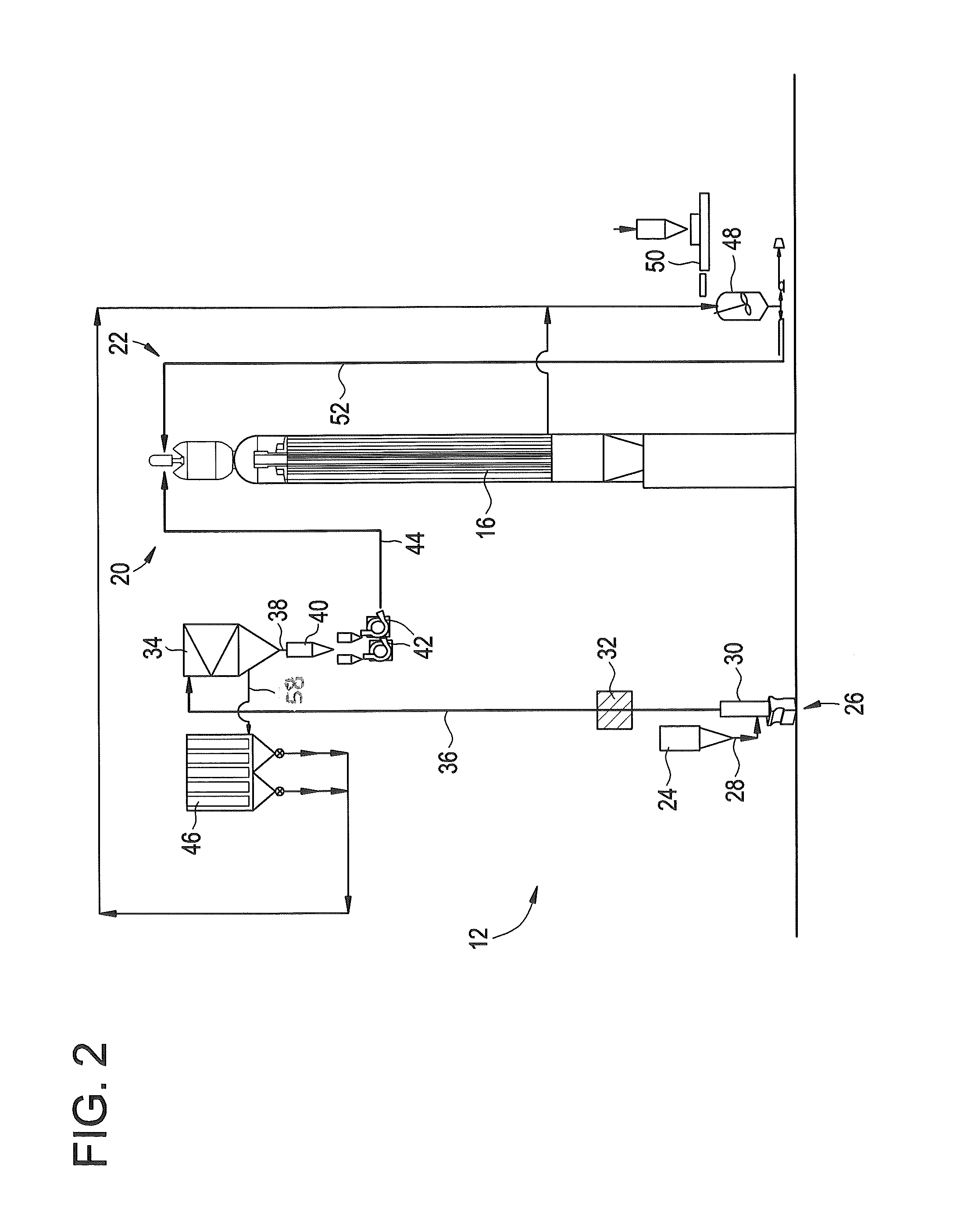
[0013]In some embodiments, as shown in FIG. 2, the fuel feed system 12 is a hybrid system that includes a dry solids feed stream 20 and a fines feed stream such as a slurry feed stream 22. The dry solids feed stream 20 includes storage, for example a storage hopper 24, for a solid carbonaceous fuel, which in an embodiment is coal. Alternatively, the fuel may be a petroleum coke, a biomass, or any other solid carbonaceous fuel that will allow the plant 10 to operate as described herein. The storage hopper 24 is connected to a feed preparation section 26 via a feed conduit 28. The feed preparation section 26 includes a pulverizer 30 or other grinding mechanism into which the fuel is fed from the storage hopper 24 via the feed conduit 28. The fuel is ground in the pulverizer 30 to a collection of particles including those of a desired size. The particles are dried by, for example, forcing hot gas across the particles. The drying may occur in the pulverizer 30, or in some embodiments, a separate particle dryer 32. Drying the fuel removes a desired amount of surface moisture from all of the various particle sizes to make subsequent handling of the particles easier and more efficient by preventing conditions such as clumping, arching and rat holing of the particles.
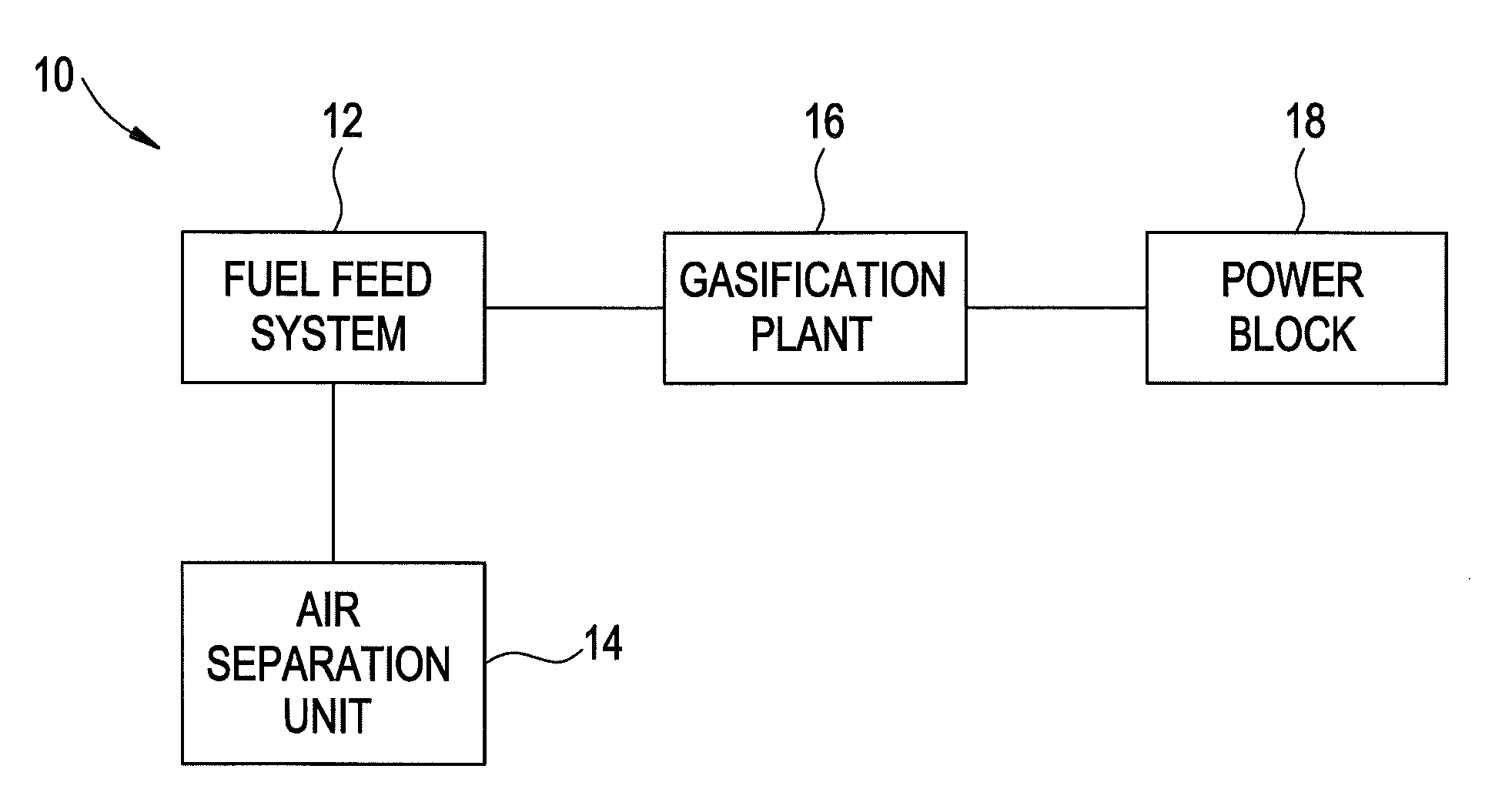
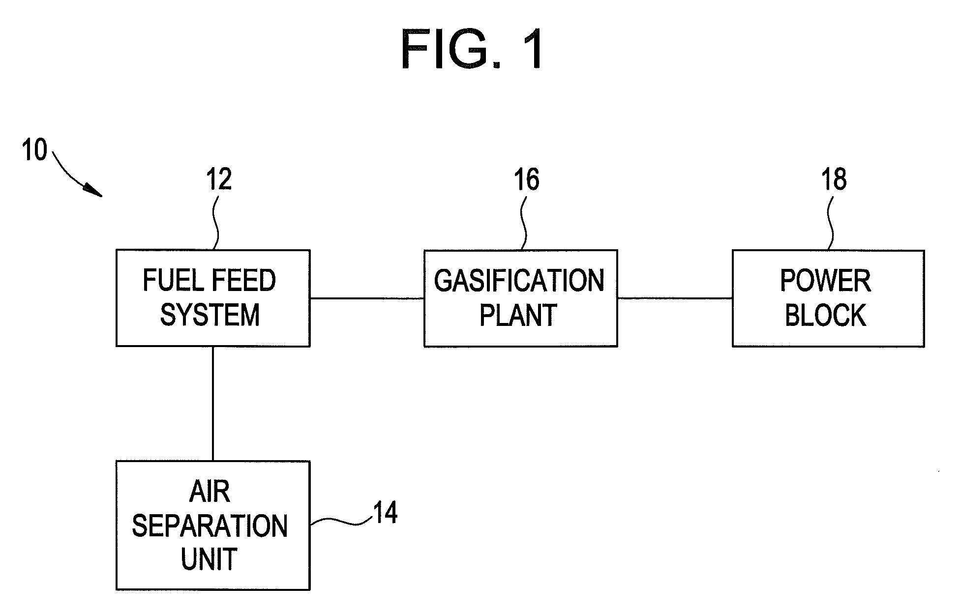
[0012]Shown in FIG. 1 is a block diagram of a portion of an embodiment of an Integrated Gasification Combined Cycle (IGCC) power generation plant 10. In the embodiment, plant 10 includes a fuel feed system 12 an air separation unit 14 coupled in flow communication with the fuel feed system 12. A gasification plant 16 is coupled in flow communication with the fuel feed system 12 and a power block 18. During operation, the air separation unit 14 uses compressed air to provide oxygen for use by the gasification plant 16. In an embodiment, the gasification plant 16 converts fuel and oxygen into a clean fuel gas, or syngas, that is combusted in power block 18 to produce electrical power.

Problems solved by technology

Smaller particles in the feed stream such as fines, however, are capable of collecting large amounts of surface moisture thereby increasing the amount of drying required to maintain reliable flow.
Further, the low mass of the fines particles reduces the feed rate capability when gravity fed from a hopper and when feeding into other equipment upstream of the gasifier.
Also, a high fines content in the feed stream increases the potential for effluent emissions from the gasification process and the potential for dust explosions when stored and handled upstream of the gasifier.

Method used


Image

  • Method and apparatus for a feed into a gasifier utilizing a slurry
  • Method and apparatus for a feed into a gasifier utilizing a slurry
  • Method and apparatus for a feed into a gasifier utilizing a slurry

Examples


Embodiment Construction

[0012]Shown in FIG. 1 is a block diagram of a portion of an embodiment of an Integrated Gasification Combined Cycle (IGCC) power generation plant 10. In the embodiment, plant 10 includes a fuel feed system 12 an air separation unit 14 coupled in flow communication with the fuel feed system 12. A gasification plant 16 is coupled in flow communication with the fuel feed system 12 and a power block 18. During operation, the air separation unit 14 uses compressed air to provide oxygen for use by the gasification plant 16. In an embodiment, the gasification plant 16 converts fuel and oxygen into a clean fuel gas, or syngas, that is combusted in power block 18 to produce electrical power.

[0013]In some embodiments, as shown in FIG. 2, the fuel feed system 12 is a hybrid system that includes a dry solids feed stream 20 and a fines feed stream such as a slurry feed stream 22. The dry solids feed stream 20 includes storage, for example a storage hopper 24, for a solid carbonaceous fuel, which...


PUM


Abstract

Disclosed is a feed system for a gasifier including a grinding mechanism capable of grinding a feedstock into particles of desired particle sizes. The particle sizes include solids particles larger than a first threshold size and raw fines particles smaller than a second threshold size. At least one solids separation device is capable of separating the solids particles from the fines particles and at least one solids conduit conveys the solids particles to a gasification plant while the fines particles are also conveyed to the gasification plant. Further disclosed is a method for feeding stock into a gasifier including conveying a feedstock into a grinding mechanism and grinding the feedstock into particles of desired sizes. Solids particles larger than a first threshold size are separated from fines particles smaller than a second threshold size and the solids particles and the fines particles are conveyed toward the gasification plant.

Description

BACKGROUND OF THE INVENTION[0001]The subject invention relates generally to gasification systems and processes, such as those used in Integrated Gasification Combined Cycle (IGCC) power generation. More particularly, the subject invention relates to fuel feed apparatus and methods for a gasification system.[0002]Gasification is a process for the production of power, chemicals, and industrial gases from carbonaceous or hydrocarbon feedstocks such as coal, heavy oil, and petroleum coke. Gasification converts carbonaceous or hydrocarbon feedstocks into synthesis gas, also known as syngas, comprising primarily hydrogen and carbon monoxide. The resultant syngas is a feedstock for making useful organic compounds or can be used as a clean fuel to produce power.[0003]In a typical gasification plant having a dry solids feed system, the feedstock, such as coal, is introduced to a grinder where it is ground into solids particles of a predetermined size. While the grinding process produces soli...

Claims


Application Information

Patent Timeline
Patent Type & Authority Patents(United States)
IPC IPC(8): B02C19/00
CPCC10J3/30C10J3/506Y02E20/18C10J2300/0906Y02E20/16C10J2300/0959C10J2300/1653C10J2300/1678C10J2300/093
Inventor RUSSELL, STEVEN CRAIGAVAGLIANO, AARON JOHN
Owner AIR PROD & CHEM INC
Learn More