Winch including rotatable tie structure
a rotatable tie and winch technology, applied in the direction of winding mechanisms, hoisting equipment, etc., can solve the problems of increasing the amount of time and effort in servicing the winch components and/or attaching/, and achieve the effect of increasing the amount of time and effort in servicing, easy and quick coupling, and increasing the access to mounting fasteners
- Summary
- Abstract
- Description
- Claims
- Application Information
AI Technical Summary
Benefits of technology
Problems solved by technology
Method used
Image
Examples
second embodiment
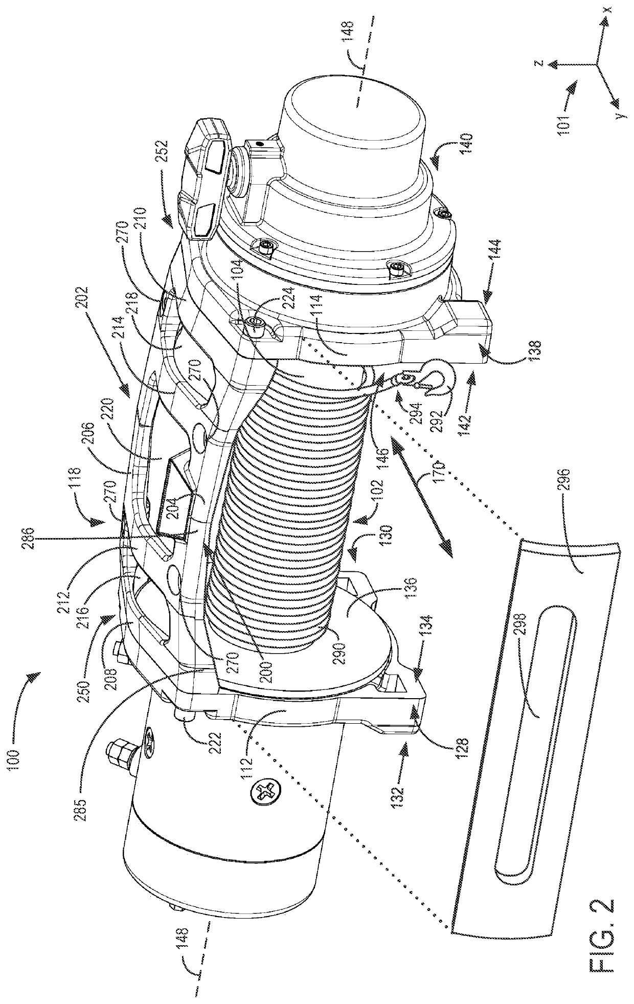
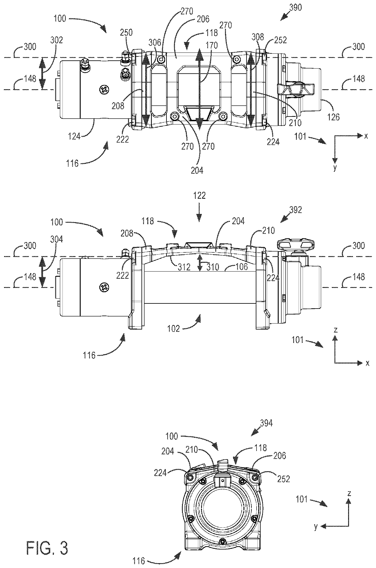
[0049]In the second embodiment shown by FIG. 8 (e.g., shown by first view 800 and second view 802), the rotational axis 300 may be positioned such that the rotational axis 300 intersects both of the first fastener 222 and the third fastener 224 (shown by FIG. 2) when the first fastener 222 and third fastener 224 are coupled with the associated apertures of the tie structure and drum supports. In other words, the first fastener 222 couples to the tie structure 118 at a location proximate to the notch 850, and the third fastener 224 couples to the tie structure 118 at a location proximate to the notch 852. In order to rotate the tie structure 118 around rotational axis 300 when the rotational axis 300 intersects the first fastener 222 and the third fastener 224 (e.g., when the rotational axis 300 is in the position indicated by arrow 860), the second fastener 250 and fourth fastener 252 are removed from the tie structure 118, while the first fastener 222 and third fastener 224 remain ...
third embodiment
[0051]In the third embodiment shown by FIG. 9 (e.g., shown by first view 900 and second view 902), the rotational axis 300 may be positioned according to a preference of the operator. In one example, the rotational axis 300 may intersect both of the second fastener 250 and the fourth fastener 252 when the second fastener 250 and fourth fastener 252 are coupled with the associated apertures of the tie structure and drum supports, and when the first fastener 222 and third fastener 224 are removed from the tie structure 118 and winch 100. In other words, the rotational axis 300 may be in the position indicated by arrow 906. In this configuration, the tie structure 118 may rotate according to the embodiment shown by FIGS. 1-7 and described above. In other words, the tie structure 118 rotates away from the drum 102 and away from the first end 128 and second end 130 of the first drum support 112 and the first end 138 and second end 140 of the second drum support 114. For example, the seco...
first embodiment
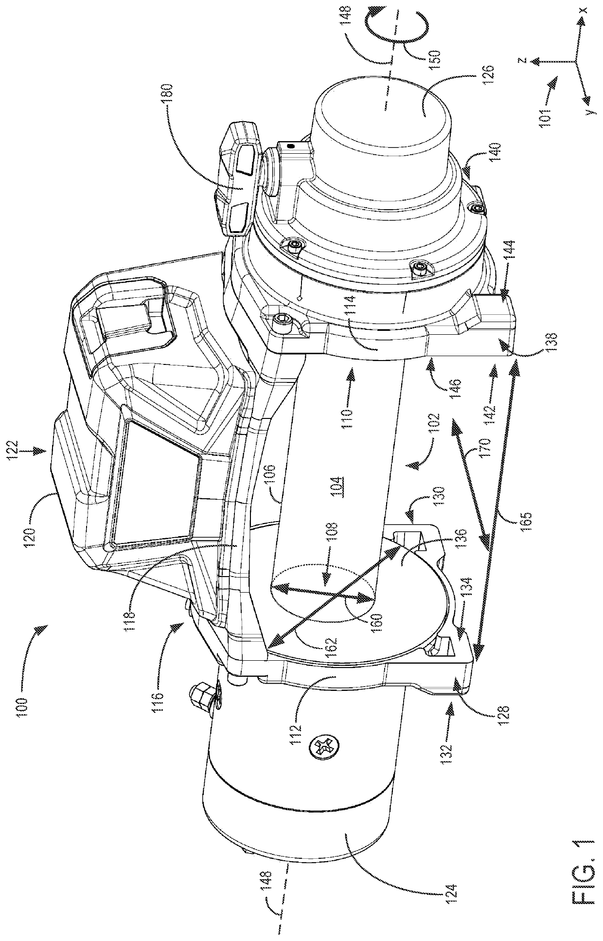
[0053]By configuring the winch and tie structure as described above with reference to FIGS. 1-9, the tie structure may rotate relative to the housing of the winch without completely decoupling the tie structure from the winch. For example (as in the first embodiment described above), the fasteners coupled to the tie structure at the first end of the first drum support and the first end of the second drum support may be removed, while the fasteners coupled to the tie structure at the second end of the first drum support and the second end of the second drum support may remain fastened. The tie structure may then pivot along the rotational axis intersecting the remaining fasteners, with the notches of the tie structure providing an open space surrounding the drum flanges to increase the rotational range of the tie structure. In this way, an operator of the winch may move the tie structure (and the control unit, if coupled with the tie structure) away from the drum in order to access t...
PUM
 Abstract
Description
Claims
Application Information
 - R&D
- Intellectual Property
- Life Sciences
- Materials
- Tech Scout
- Unparalleled Data Quality
- Higher Quality Content
- 60% Fewer Hallucinations
Browse by: Latest US Patents, China's latest patents, Technical Efficacy Thesaurus, Application Domain, Technology Topic, Popular Technical Reports.
© 2025 PatSnap. All rights reserved.Legal|Privacy policy|Modern Slavery Act Transparency Statement|Sitemap|About US| Contact US: help@patsnap.com


