Nozzle plate for fuel injection device
- Summary
- Abstract
- Description
- Claims
- Application Information
AI Technical Summary
Benefits of technology
Problems solved by technology
Method used
Image
Examples
first embodiment
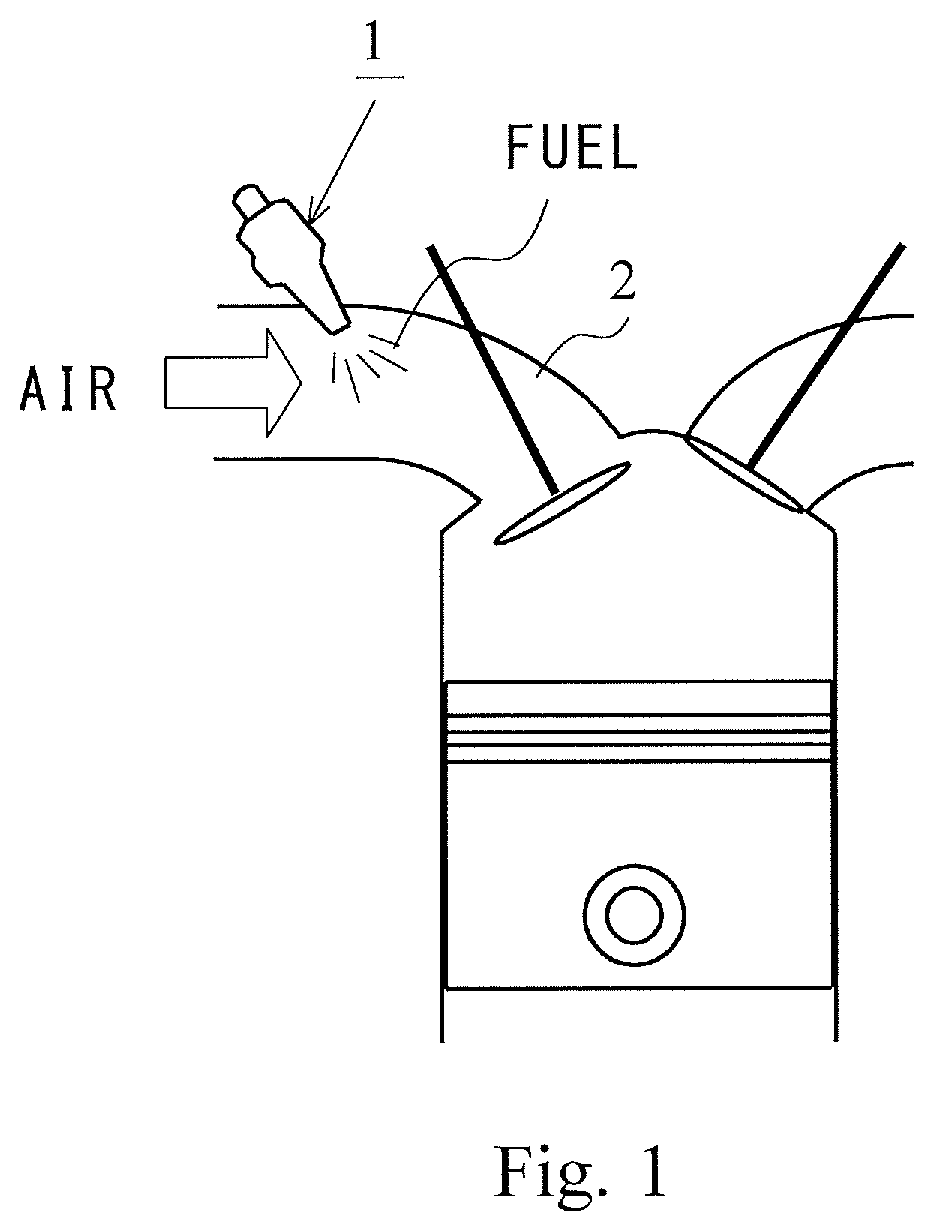
[0029]FIG. 1 is a view schematically showing an in-use state of a fuel injection device 1 on which a nozzle plate according to a first embodiment of the present invention is mounted. As shown in FIG. 1, the fuel injection device 1 of a port injection method is mounted in a middle portion of an intake pipe 2 of an engine, and is configured to generate a combustible mixed gas by injecting fuel into the inside of the intake pipe 2 and mixing the fuel and air introduced into the intake pipe 2.
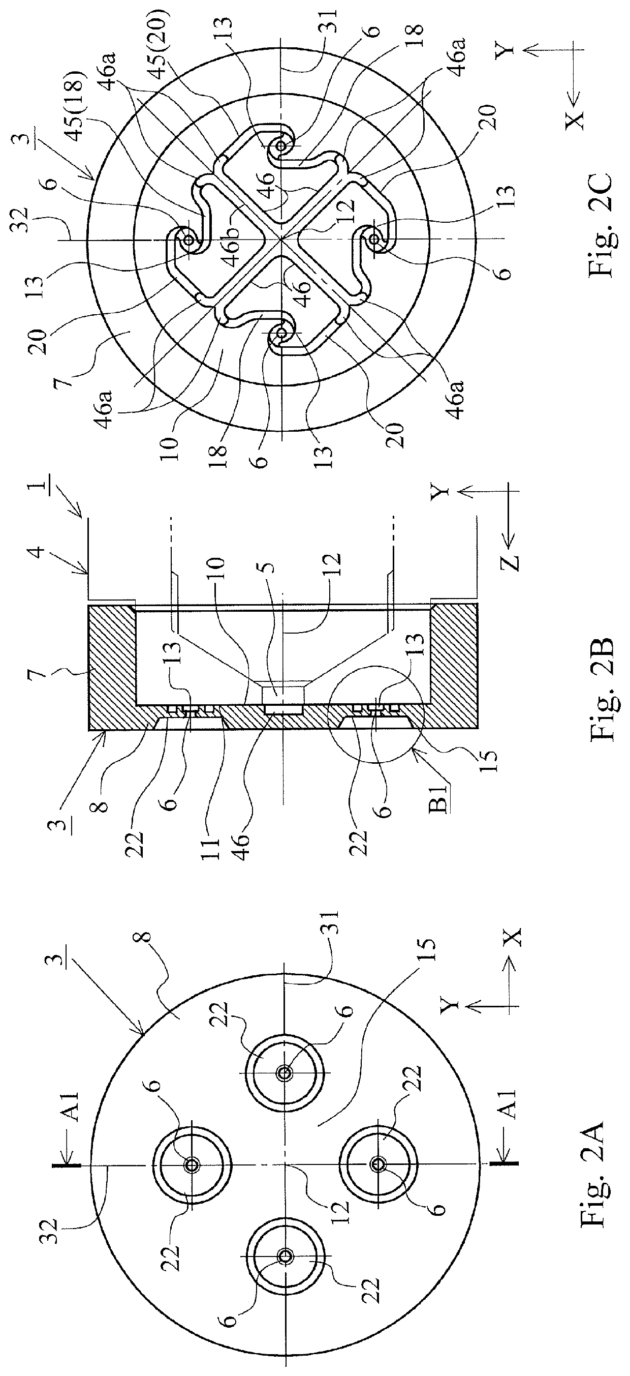
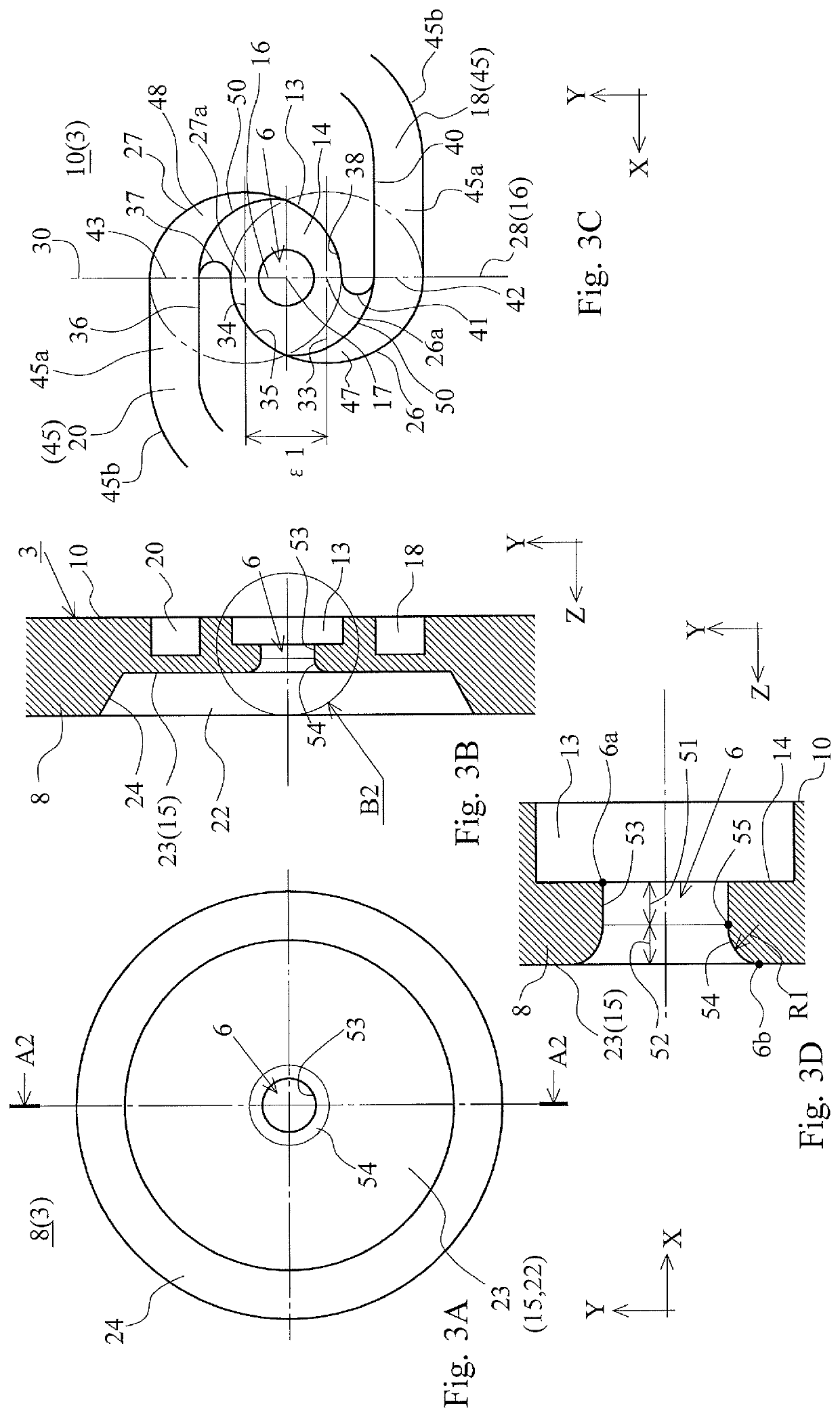
[0030]FIG. 2 and FIG. 3 are views showing a nozzle plate 3 according to the first embodiment of the present invention. FIG. 2A is a front view of the nozzle plate 3, FIG. 2B is a cross-sectional view of the nozzle plate 3 taken along a line A1-A1 in FIG. 2A, and FIG. 2C is a back view of the nozzle plate 3. FIG. 3A is an enlarged view of a part of a nozzle plate 3 (periphery of the nozzle holes 6) shown in FIG. 2A, FIG. 3B is an enlarged cross-sectional view of a portion B1 of FIG. 2B (cross-sectio...
modification 1
(Modification 1)
[0043]FIG. 4 are views showing a nozzle plate 3 according to the modification. FIG. 4A is a plan view of the nozzle plate 3, FIG. 4B is a cross-sectional view of the nozzle plate 3 taken along a line A3-A3 in FIG. 4A, and FIG. 4C is a back surface view of the nozzle plate 3. It is to be noted that, in the nozzle plate 3 of the present modification, the same reference characters as those in the nozzle plate 3 according to the first embodiment are used to represent the same component, and redundant description of already described nozzle plate 3 according to the first embodiment is omitted.
[0044]As shown in FIG. 4, the nozzle plate 3 according to the modification has a shape where the circular cylindrical fitted portion 7 of the nozzle plate 3 according to the first embodiment is omitted, and is constituted of only a part corresponding to the plate body portion 8 of the nozzle plate 3 according to the first embodiment. Other configuration of the nozzle plate 3 accordin...
modification 2
(Modification 2)
[0045]FIG. 5 shows a nozzle plate 3 according to the present modification, and correspond to FIG. 3. FIG. 5A is an enlarged view of a part of the nozzle plate 3 (periphery of the nozzle holes 6) (corresponding to FIG. 3A), FIG. 5B is a cross-sectional view taken along a line A4-A4 in FIG. 5A (corresponding to FIG. 3B), and FIG. 5C is a partial enlarged view of FIG. 5B (corresponding to FIG. 3D).
[0046]At the nozzle plate 3 according to the present modification shown in FIG. 5, configurations of the swirl chamber 13 and the first and second fuel guide channels 18 and 20 are similar to those shown in FIG. 3C. Also, a configuration of a portion near fuel-inflow end 51 of the nozzle hole 6 is similar to those shown in FIG. 3D. However, a configuration of the curved surface 54 of the portion near fuel-outflow end of the nozzle hole 6 in the nozzle plate 3 according to the present modification is different from that of the nozzle plate 3 according to the first embodiment.
[0...
PUM
 Abstract
Description
Claims
Application Information
 - R&D
- Intellectual Property
- Life Sciences
- Materials
- Tech Scout
- Unparalleled Data Quality
- Higher Quality Content
- 60% Fewer Hallucinations
Browse by: Latest US Patents, China's latest patents, Technical Efficacy Thesaurus, Application Domain, Technology Topic, Popular Technical Reports.
© 2025 PatSnap. All rights reserved.Legal|Privacy policy|Modern Slavery Act Transparency Statement|Sitemap|About US| Contact US: help@patsnap.com


