
Fuel flow control assembly of aircraft engine and method

a technology of fuel flow control and aircraft engine, which is applied in the direction of liquid fuel engines, machines/engines, efficient propulsion technologies, etc., can solve the problems of insufficient) fuel flow output at low gear rotational speed, and achieve the effect of increasing fuel flow

Active Publication Date: 2018-07-26
HAMILTON SUNDSTRAND CORP
View PDF17 Cites 3 Cited by
  • Summary
  • Abstract
  • Description
  • Claims
  • Application Information

AI Technical Summary

Benefits of technology

This patent describes a fuel flow control assembly for aircraft engines that allows for regulation of fuel flow through a pressure pad. The assembly includes a gear arrangement, a bearing structure, and a flow metering device that can restrict the fuel flow at low pressure and increase it at high pressure. The technology can help manage fuel flow for efficient engine operation.

Problems solved by technology

However, this is achieved at the expense of parasitic pump fuel flow output loss at cranking conditions, resulting in low (e.g., insufficient) fuel flow output at low rotational speeds of the gear pump such as start and windmill start or significantly larger pumps to accommodate this loss.

Method used


Image

  • Fuel flow control assembly of aircraft engine and method
  • Fuel flow control assembly of aircraft engine and method
  • Fuel flow control assembly of aircraft engine and method

Examples


Embodiment Construction

[0011]A detailed description of one or more embodiments of the disclosed apparatus and method are presented herein by way of exemplification and not limitation with reference to the Figures.

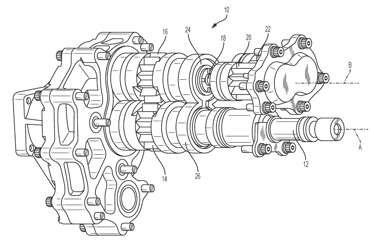
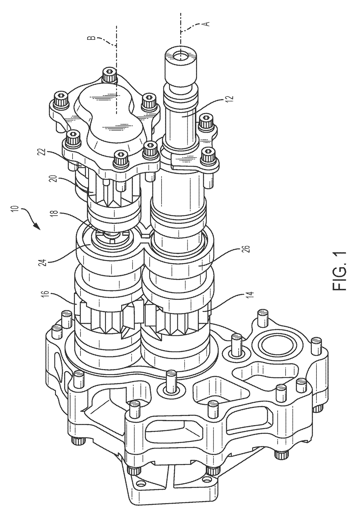
[0012]Referring to FIG. 1, a fuel gear pump assembly 10 is shown with a housing removed for illustrative purposes. The illustrated fuel gear pump assembly 10 is a dual stage gear arrangement for use in conjunction with a fuel supply system for an aircraft engine. However, it is contemplated that fuel supply systems for other applications may benefit from the embodiments described herein. Although a two stage gear arrangement is illustrated and described herein, it is to be appreciated that the embodiments described herein may be incorporated into other multi-stage arrangements or a single stage arrangement.

[0013]The fuel gear pump assembly 10 provides fuel flows and pressures for various engine performance functions. The fuel gear pump assembly 10 includes an input drive shaft 12 (e.g., first sha...


PUM


Abstract

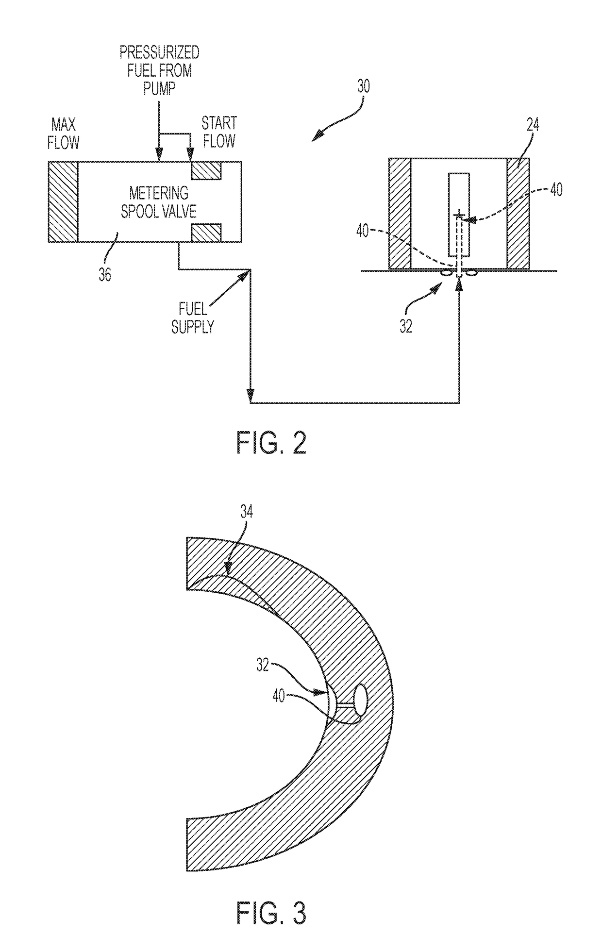
A fuel flow control assembly for an aircraft engine. The assembly includes a gear arrangement having a shaft. Also included is a bearing structure operatively coupled to each shaft. Further included is a pressure pad disposed adjacent the bearing structure, the pressure pad having a radially extending port for receiving a fuel flow. Yet further included is a flow metering device in flow communication with the port of the pressure pad to restrict the fuel flow at a low pressure operating condition and open the port to increase the fuel flow at a high pressure operating condition.

Description

BACKGROUND[0001]Exemplary embodiments pertain to the art of fuel supply systems for aircraft engines and, more particularly, to a fuel metering and fuel supply assembly for such systems, as well as a method.[0002]Aircraft gas turbine engines receive pressurized fuel from fuel gear pumps. The gear pump must be compact, lightweight and robust. The gear pump must perform over a wide operational range while providing critical fuel flows and pressures for various engine performance functions. Typically, these gear pumps receive rotational power from an accessory gearbox through an input drive shaft. Such gear pumps are arranged in a dual stage comprising a driving gear and a driven gear. The rotational power from the input shaft is transferred from one stage to the other stage through the driven gear and its coupling shaft. Each gear stage contains gears supported by journal bearings. The load of the gear shafts is supported by journal bearings operating on both the hydrostatic pressure ...

Claims


Application Information

Patent Timeline
Patent Type & Authority Applications(United States)
IPC IPC(8): F04C14/00F04C15/00F04C2/14F04C13/00
CPCF04C14/00F04C13/00F04C2/14F04C15/0026F01D25/166F01D25/18F04C2/18F02C7/22F02C9/263F04C2210/203F04C2240/54F05D2240/53Y02T50/60
Inventor VEILLEUX, JR., LEO J.RIBAROV, LUBOMIR A.
Owner HAMILTON SUNDSTRAND CORP
Learn More