
Fuel flow control system and method for engine start

a fuel flow control and engine start technology, applied in the direction of engine starters, machines/engines, turbine/propulsion engine ignition, etc., can solve the problems of inability to efficiently start the engine under all conditions, the engine starting process involves some challenges, and the single fuel and acceleration schedule cannot be used to achieve the effect of efficient starting the engin

Active Publication Date: 2020-05-14
PRATT & WHITNEY CANADA CORP
View PDF0 Cites 3 Cited by
  • Summary
  • Abstract
  • Description
  • Claims
  • Application Information

AI Technical Summary

Benefits of technology

The patent describes a method for controlling fuel flow to an engine during start-up. The method involves injecting fuel into the engine according to a schedule that determines the minimum amount of fuel needed to achieve light-off. The system monitors various operating parameters of the engine and detects when flameout occurs (when there is no ignition of the fuel air mixture). In response to flameout, the minimum fuel flow limit is increased and the fuel is injected into the engine according to an adjusted schedule. The technical effect of the patent is to improve the starting process of engines, ensuring optimal fuel injection and minimizing fuel waste during start-up.

Problems solved by technology

The engine starting process however involves some challenges as different extremes of the ground and flight envelope may have conflicting requirements.
For instance, for a same altitude and temperature, a cold soak static engine start would not allow the same acceleration as a warm engine being restarted in an aircraft flying at high speed.
As a result, a single fuel and acceleration schedule cannot be used to efficiently start the engine under all conditions while avoiding undesirable behavior, such as compressor stall, over temperature, engine hang or flameout.

Method used


Image

  • Fuel flow control system and method for engine start
  • Fuel flow control system and method for engine start
  • Fuel flow control system and method for engine start

Examples


Embodiment Construction

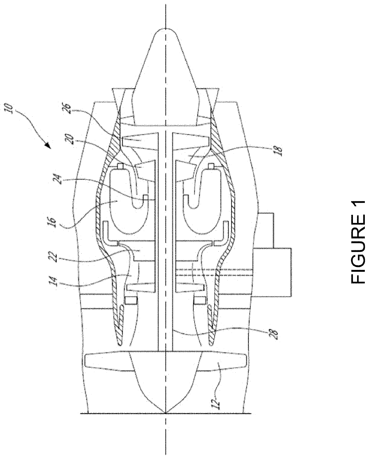
[0015]FIG. 1 illustrates a gas turbine engine 10 of a type preferably provided for use in subsonic flight, generally comprising in serial flow communication, a fan 12 through which ambient air is propelled, a compressor section 14 for pressurizing the air, a combustor 16 in which the compressed air is mixed with fuel and ignited for generating an annular stream of hot combustion gases, and a turbine section 18 for extracting energy from the combustion gases. High pressure rotor(s) 20 of the turbine section 18 are drivingly engaged to high pressure rotor(s) 22 of the compressor section 14 through a high pressure shaft 24. Low pressure rotor(s) 26 of the turbine section 18 are drivingly engaged to the fan rotor 12 and to other low pressure rotor(s) (not shown) of the compressor section 14 through a low pressure shaft 28 extending within the high pressure shaft 24 and rotating independently therefrom.

[0016]Although illustrated as a turbofan engine, the gas turbine engine 10 may alterna...


PUM


Abstract

Systems and methods for controlling fuel flow to an engine during start are provided. Fuel is caused to be injected into a combustor of the engine according to a first fuel schedule defining a minimum fuel flow limit required to achieve light-off of the engine, the minimum fuel flow limit set at an initial value. Following light-off of the engine, at least one operating parameter of the engine is monitored. Based on the at least one operating parameter, occurrence of flameout in the engine is detected. In response to detecting occurrence of flameout in the engine, the minimum fuel flow limit is increased from the initial value to a first value to obtain an adjusted fuel schedule, and fuel is caused to be injected into the combustor according to the adjusted fuel schedule.

Description

TECHNICAL FIELD[0001]The present disclosure relates generally to fuel flow control for engine start.BACKGROUND OF THE ART[0002]In a gas turbine engine, continuous inlet air is compressed, mixed with fuel in an inflammable proportion, and exposed to an ignition source to ignite the mixture which then continues to burn to produce combustion products. The engine starting process however involves some challenges as different extremes of the ground and flight envelope may have conflicting requirements. For instance, for a same altitude and temperature, a cold soak static engine start would not allow the same acceleration as a warm engine being restarted in an aircraft flying at high speed. As a result, a single fuel and acceleration schedule cannot be used to efficiently start the engine under all conditions while avoiding undesirable behavior, such as compressor stall, over temperature, engine hang or flameout.[0003]Therefore, improvements are needed.SUMMARY[0004]In accordance with a br...

Claims


Application Information

Patent Timeline
Patent Type & Authority Applications(United States)
IPC IPC(8): F02C9/26F02C7/262F02C3/06
CPCF02C9/26F02C7/262F05D2220/32F02C3/06F02C7/26F05D2270/092
Inventor DES ROCHES-DIONNE, NICOLASLAMARRE, SYLVAINLOPEZ, SIMON
Owner PRATT & WHITNEY CANADA CORP
Learn More