Method for operating a LNG fuelled marine vessel

a fuelled marine vessel and fuel technology, applied in the direction of liquid transfer devices, container discharging methods, passenger handling devices, etc., can solve the problems harmful to the supply procedure and the piping arrangement of the bunkering line, and the effect of long time-consuming bunkering operation

Inactive Publication Date: 2011-07-28
WARTSILA FINLAND OY
View PDF6 Cites 20 Cited by
  • Summary
  • Abstract
  • Description
  • Claims
  • Application Information

AI Technical Summary

Benefits of technology

[0006]An object of the present invention is to avoid the drawbacks of the prior art and to provide for an efficient transfer of fuel, particularly LNG, while maintaining a controlled fuel flow. This object is achieved by the method according to claim 1.

Problems solved by technology

The bunkering operation of a LNG fuelled marine vessel usually takes a long time.
The two-phase flow causes control problems and pressure pulses, which are harmful for the supply procedure and for the piping arrangements of the bunkering line.
The bunkering operation consequently takes a very long time.
A typical practice and trend in marine vessel operation of today is shortened port times and high operating speeds, the latter with high energy consumption, which would necessitate a transfer of large amounts of fuel in a short time.
Such fast transfer of fuel is not available in the prior art.

Method used


Image

  • Method for operating a LNG fuelled marine vessel
  • Method for operating a LNG fuelled marine vessel
  • Method for operating a LNG fuelled marine vessel

Examples


first embodiment

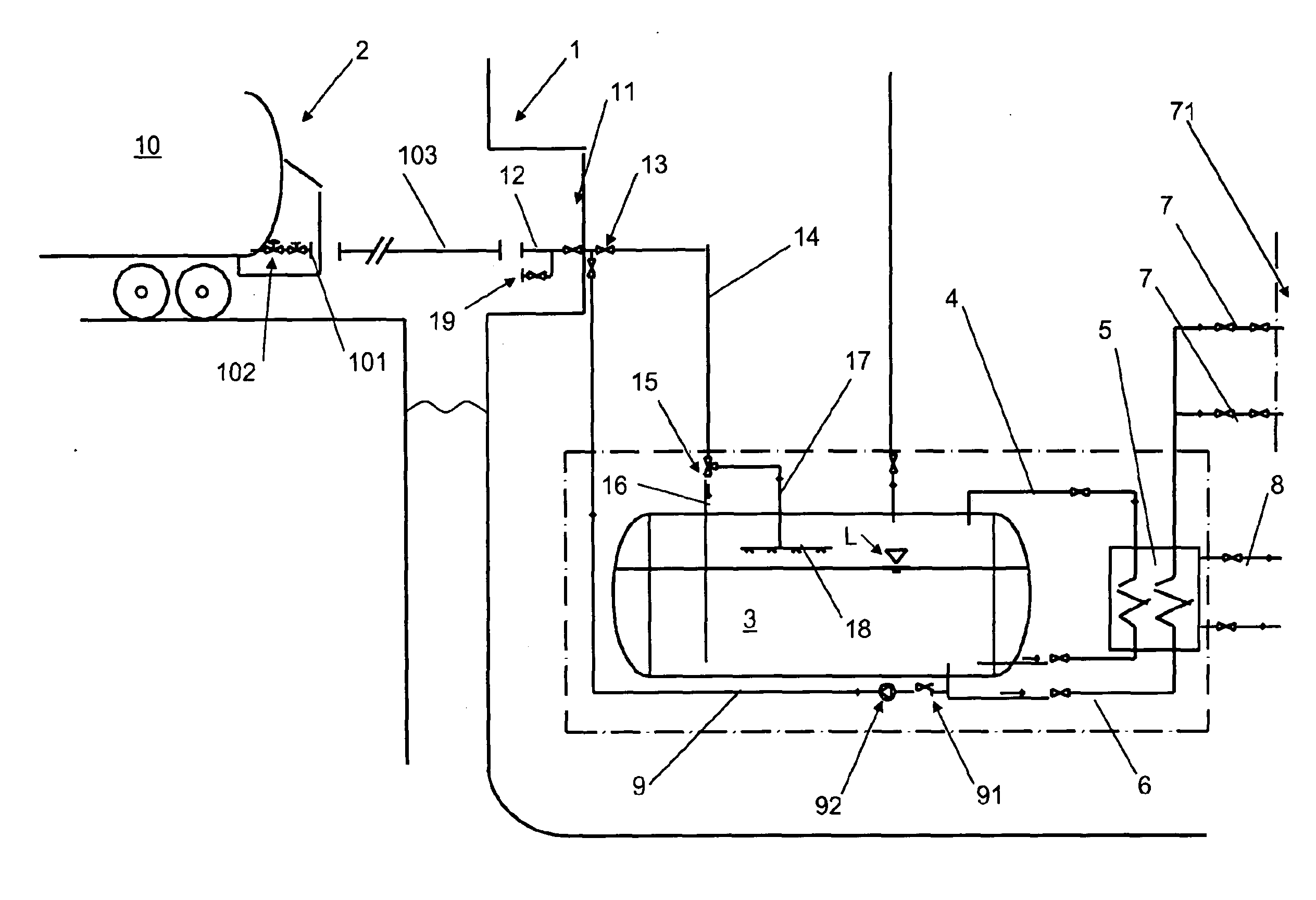
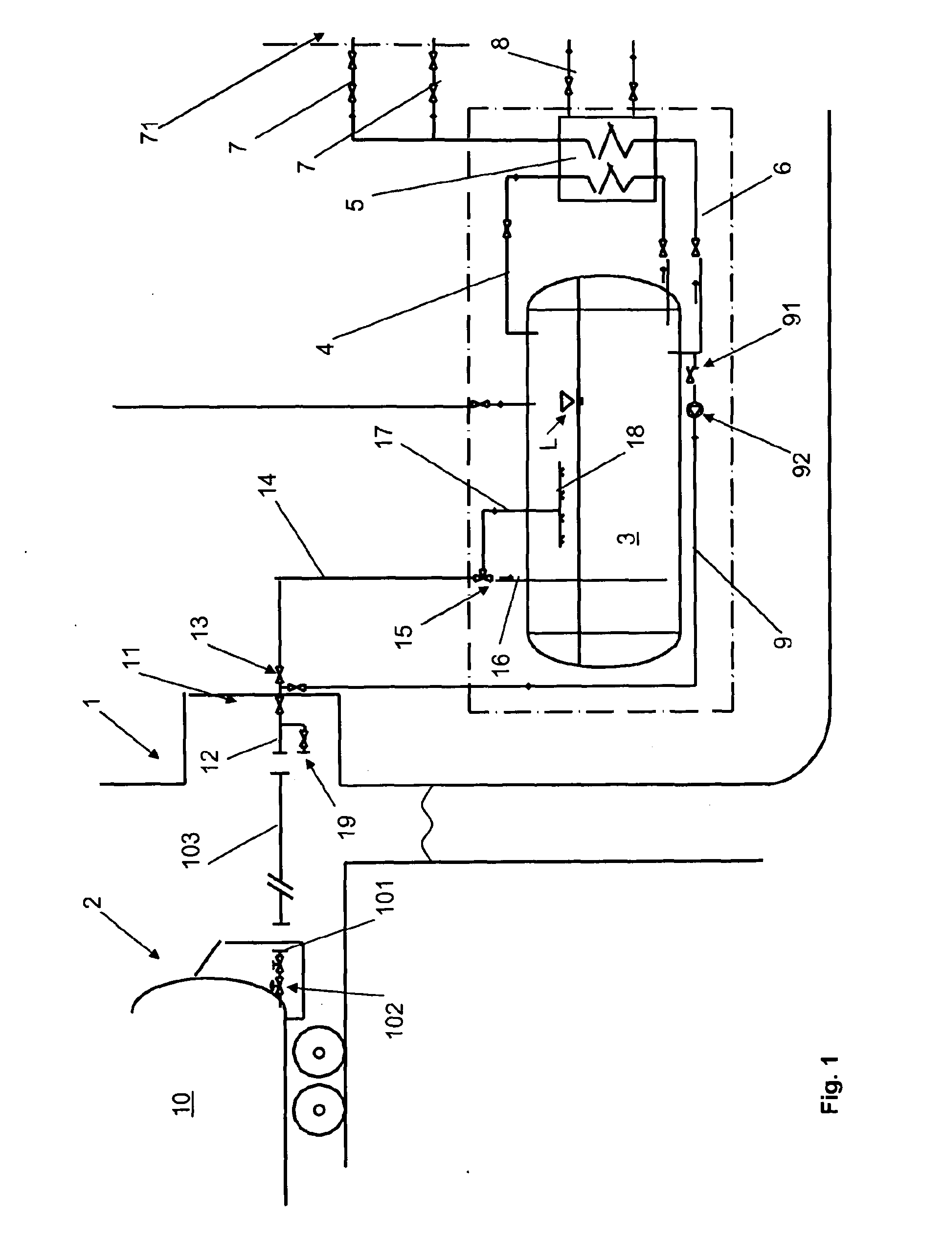
[0015]FIG. 1, illustrating the invention, shows a marine vessel 1 at a bunkering facility 2, such as a port. The marine vessel 1 is indicated by a line schematically showing the side shell of the marine vessel. The side shell accommodates a bunker station 11 comprising an inlet pipe 12 with appropriate valve means. The inlet pipe 12 leads to a bunkering line 14, provided with a first emergency shut down valve 13, which in turn leads to a LNG storage tank 3 on the marine vessel 1. The LNG storage tank 3 is connected by way of a discharge conduit 6 and a fuel feed line 7 to a power plant (indicated schematically by reference numeral 71) of the marine vessel 1. A liquid level of the LNG in the LNG storage tank is indicated by reference sign L.

[0016]The bunkering line 14, in this embodiment, includes a two-way valve 15, a first branch pipe 16, which is connected to the two-way valve 15 and which opens directly into the LNG storage tank 3, and a second branch pipe 17, which is connected ...

second embodiment

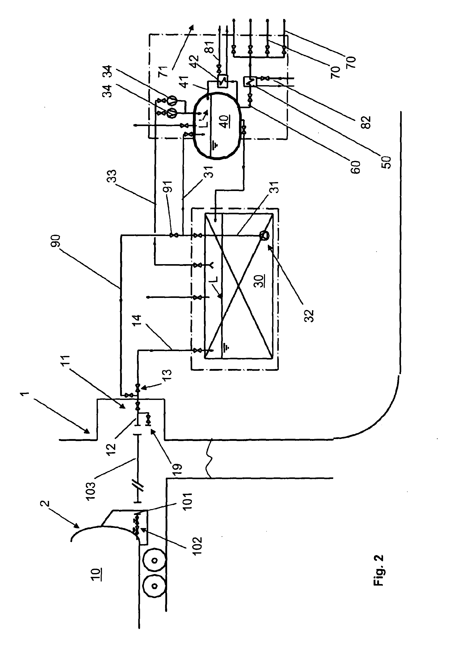
[0036]FIG. 2, illustrating the invention, shows a marine vessel 1 at a bunkering facility 2, such as a port. The marine vessel 1 is indicated by a line schematically showing the side shell of the marine vessel. The side shell accommodates a bunker station 11 comprising an inlet pipe 12 with appropriate valve means. The inlet pipe 12 leads to a bunkering line 14, provided with a first emergency shut down valve 13, which in turn leads to a LNG storage tank 30 on the marine vessel 1.

[0037]The bunkering line 14 leads directly to the LNG storage tank 30, which is connected to a separate fuel feed tank 40, which is a heat insulated pressure vessel and which is of a considerably smaller size than the LNG storage tank 30. The LNG storage tank 30 is under atmospheric pressure, i.e. in practice under the hydrostatic pressure caused by the LNG. A liquid level of the LNG in the LNG storage tank is indicated by reference sign L.

[0038]The inlet pipe 12 is provided with a purge connection 19 in or...


PUM


Abstract

The invention relates to a method and system for operating a LNG fuelled marine vessel. The marine vessel (1) comprises a LNG storage tank (3) and a LNG fuelled power plant (71). LNG is stored in the LNG storage tank, and in connection with a bunkering operation the marine vessel is supplied with LNG by connecting a source of LNG to a bunkering line (14) of the marine vessel and subsequently supplying the marine vessel with LNG through the bunkering line. In order to achieve a faster bunkering operation the bunkering line (14) is cooled down prior to the bunkering operation.

Description

TECHNICAL FIELD[0001]Method for operating a LNG fuelled marine vessel, which marine vessel comprises a LNG storage tank and a LNG fuelled power plant, in which method LNG is stored in the LNG storage tank, and in which method in connection with a bunkering operation the marine vessel is supplied with LNG by connecting a source of LNG to a bunkering line of the marine vessel and subsequently supplying the marine vessel with LNG through the bunkering line according to the preamble of claim 1. The invention also relates to an operating system according to the preamble of claim 6.BACKGROUND ART[0002]Marine vessels can be fuelled by LNG (Liquefied Natural Gas). Clearly, as also with LNG, marine vessels need to be refuelled or bunkered at certain intervals. The bunkering operation usually takes place in port, but may also take place at other locations, such as at a floating bunkering facility out at sea.[0003]The bunkering operation of a LNG fuelled marine vessel usually takes a long time...

Claims


Application Information

Patent Timeline
Patent Type & Authority Applications(United States)
IPC IPC(8): F17C13/08B67D9/00
CPCB63B27/24Y02T70/5263B67D9/00F17C6/00F17C9/02F17C2221/033F17C2223/0161F17C2223/033F17C2223/046F17C2223/047F17C2225/0123F17C2225/0161F17C2225/033F17C2225/044F17C2225/047F17C2227/0107F17C2227/0135F17C2227/0157F17C2227/0178F17C2227/044F17C2260/025F17C2265/037F17C2265/061F17C2265/066F17C2270/0105F17C2270/0136F17C2270/0171B63J2099/003Y02T70/50F17C5/04B67D9/02
Inventor SIPILA, TUOMASLEVANDER, OSKAR
Owner WARTSILA FINLAND OY
Why Eureka
Try Eureka