
Fuel injection nozzle for dme fuel, and diesel engine including the fuel injection nozzle for dme fuel

Inactive Publication Date: 2005-11-17
BOSCH AUTOMOTIVE SYST CORP
View PDF6 Cites 4 Cited by
  • Summary
  • Abstract
  • Description
  • Claims
  • Application Information

AI Technical Summary

Benefits of technology

[0014] By this, according to the fuel injection nozzle for DME fuel of the second aspect of the invention, since the ratio L3 / L2 of the center diameter and the seat diameter is set to 0.70 or higher, the minimum flow path area at full lift regulated by the center diameter can be increased, and by that, the foregoing operation and effect of the invention of the first aspect can be obtained.

Problems solved by technology

However, atmospheric pollution by the diesel engine becomes a problem in recent years, and as measures against the atmospheric pollution, attention is paid to using DME, whose exhaust is clean, as fuel instead of the light oil.
Thus, a conventional diesel engine using light oil as fuel can not be used directly as a diesel engine using DME as fuel.
However, in an existing diesel engine vehicle using light oil as fuel, in case the mounted whole diesel engine must be exchanged with a diesel engine of DME fuel, it takes very high cost, labor, and time, and this can not be said to be realistic.
Accordingly, even if a diesel engine vehicle of DME fuel is put to practical use, the replacing of existing light oil fuel diesel engine vehicles is not smoothly carried out, and by that, the spread of the diesel engine of DME fuel is much delayed, and there is a fear that measures against the worrying destruction of the environment and global warming are delayed, and the exhaustion of oil resources is hastened.

Method used


Image

  • Fuel injection nozzle for dme fuel, and diesel engine including the fuel injection nozzle for dme fuel
  • Fuel injection nozzle for dme fuel, and diesel engine including the fuel injection nozzle for dme fuel
  • Fuel injection nozzle for dme fuel, and diesel engine including the fuel injection nozzle for dme fuel

Examples


Embodiment Construction

[0033] Hereinafter, embodiments of the invention will be described with reference to drawings while a comparison is made to a conventional fuel injection nozzle of a diesel engine using light oil as fuel.

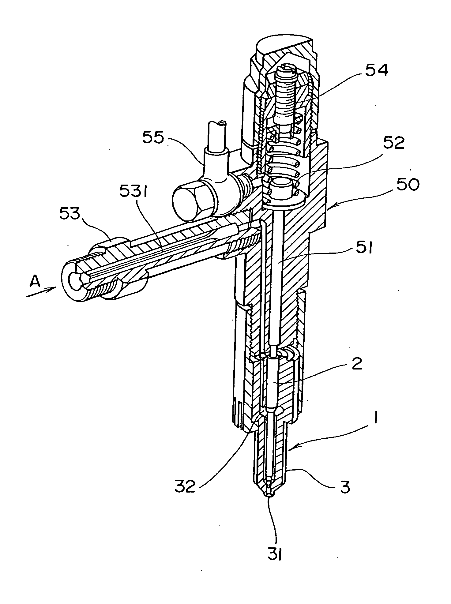
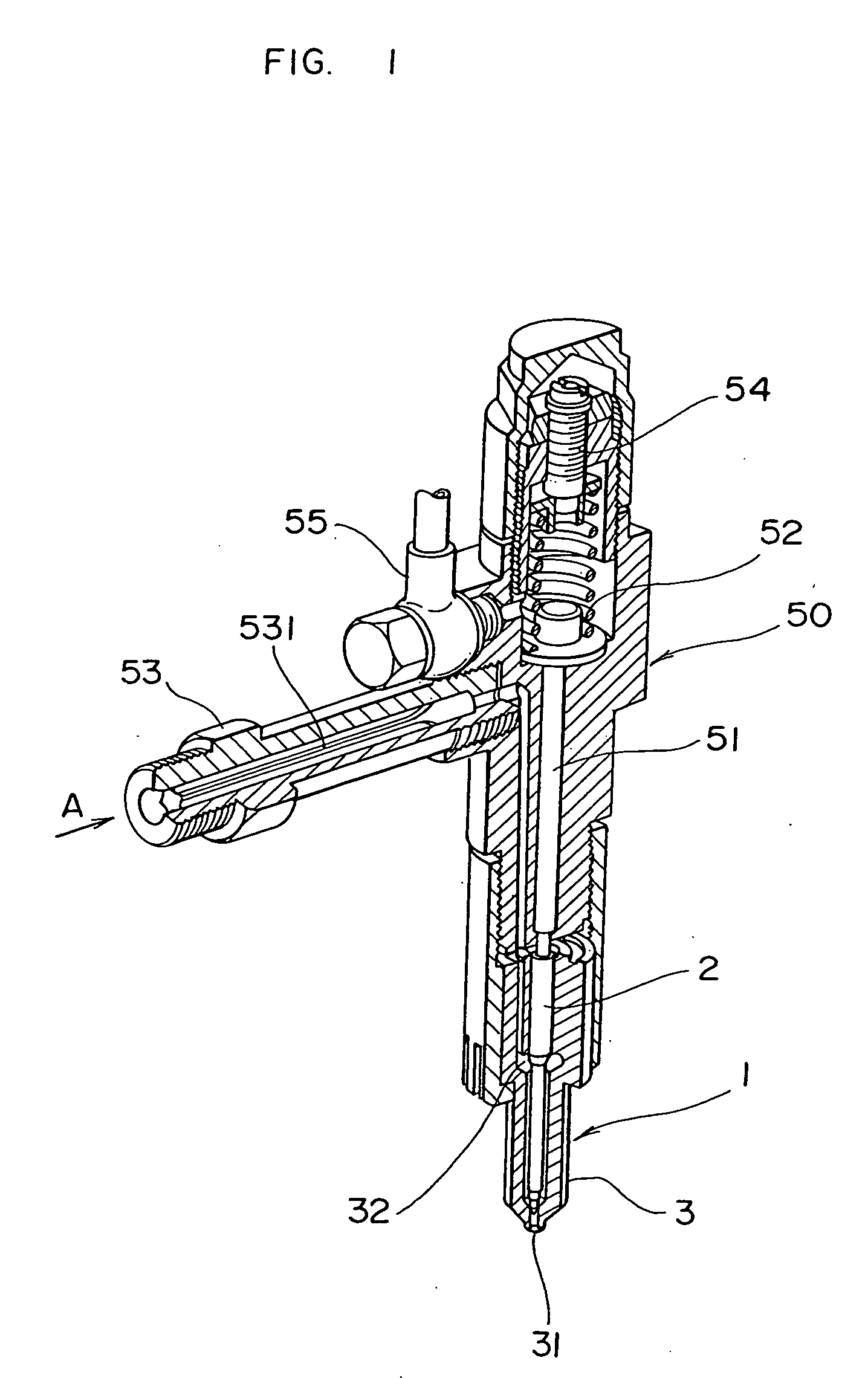
[0034]FIG. 1 is a sectional view showing a rough structure of a nozzle holder including a fuel injection nozzle as “fuel injection nozzle for DME fuel” according to the invention.

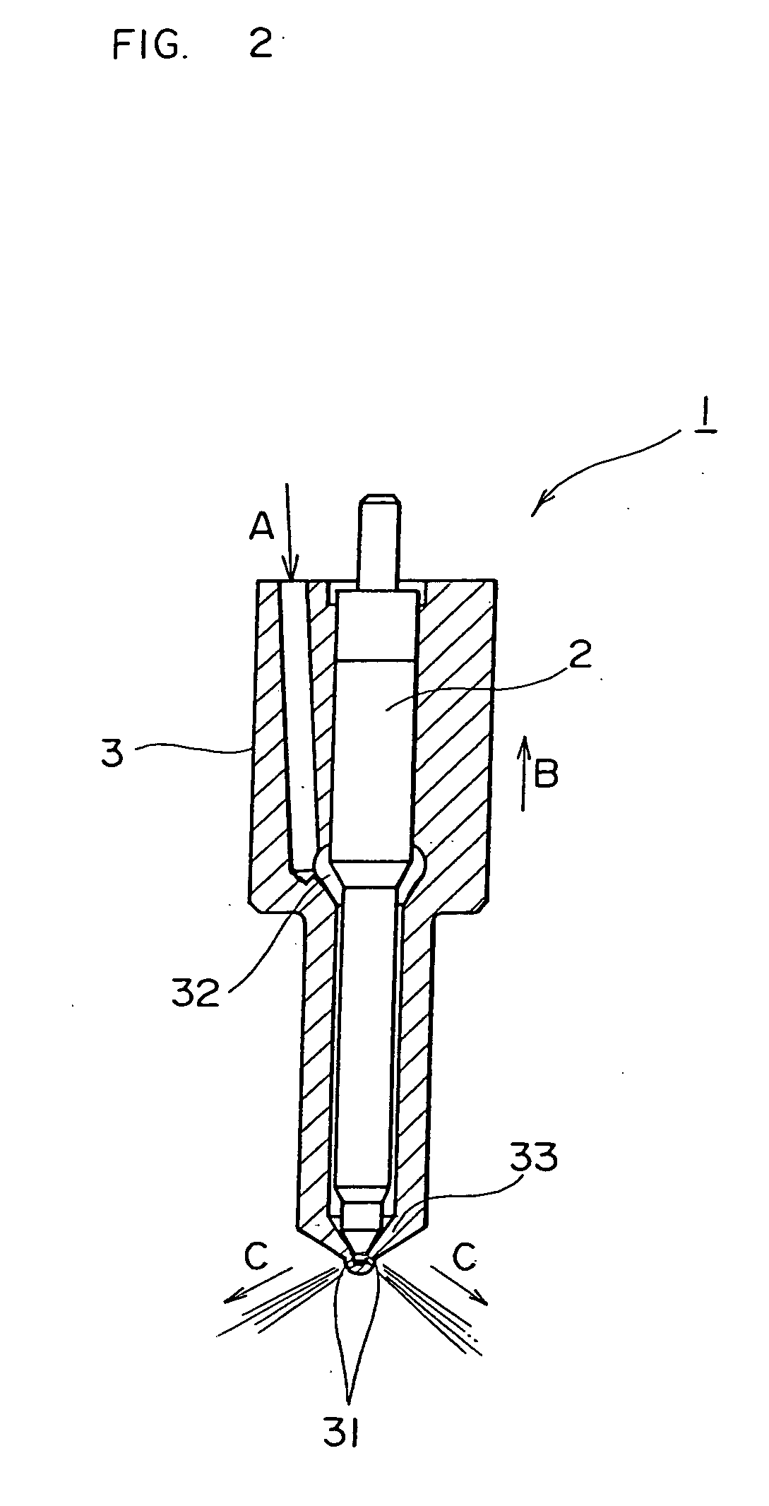
[0035] A fuel injection nozzle 1 is a long stem type hole nozzle, and is disposed in each combustion chamber of a diesel engine by a nozzle holder 50. A DME fuel pressurized to a high pressure is introduced (reference character A) into a nozzle body 3 of the fuel injection nozzle 1 from an inlet connector 53 through a filter 531. A nozzle spring 52 at an upper part of a push rod 51 regulates an injection start pressure of the fuel injection nozzle 1, and its adjustment is performed by an adjusting screw 54. Lubrication of a sliding part of the fuel injection nozzle 1 is performed by part of the DME fuel, ...


PUM


Abstract

An existing diesel engine vehicle of light oil fuel is enabled to run as a diesel engine vehicle using DME as fuel without exchanging a whole diesel engine and at very low cost and easily. The shape of a tip part 21 of a needle valve 2 is set by a center diameter L3 for regulating a minimum flow path area at full lift of a fuel injection nozzle 1, a seat diameter L2 of a seat part 211 coming in contact with a valve seat part 33 and blocking communication with a fuel injection hole 31, and a shaft diameter L1, and a tip end angle is about 92 degrees. The center diameter L3 is set to φ2.5 mm, the seat diameter L2 is set to φ3.0 mm, and the shaft diameter L1 is set to φ3.25 mm. The ratio of the center diameter L3 and the seat diameter L2 is L3 / L2=2.5 mm / 3.0 mm=about 0.833, and the ratio of the seat diameter L2 and the shaft diameter L1 is L2 / L1=3.0 mm / 3.25 mm=about 0.92.

Description

TECHNICAL FIELD [0001] The present invention relates to a fuel injection nozzle for DME fuel in a diesel engine using DME (DiMethyl Ether) as fuel. BACKGROUND ART [0002] A conventional fuel injection nozzle of a diesel engine using light oil as fuel includes, for example, a needle valve 2 as shown in FIG. 9. As shown in FIG. 10, in a state where an outer peripheral surface of a tip part 21 of the needle valve 2 is seated on a valve seat part 33, communication of light oil fuel to a fuel injection port 31 of a nozzle body 3 is blocked and a fuel injection nozzle 1 is put in a valve closed state (for example, see JP-A-11-13576). The tip part 21 of the needle valve 2 has such a shape that the ratio of a shaft diameter L1 and a seat diameter L2 of a seat part 211 coming in contact with the valve seat part 33 becomes L2 / L1=0.60 to 0.75. Besides, it has such a shape that the ratio of the seat diameter L2 and a center diameter L3 for regulating a minimum flow path area at full lift of the ...

Claims


Application Information

Patent Timeline
IPC IPC(8): F02M21/08F02B3/06F02M61/12F02M61/18
CPCF02B3/06F02M61/12F02M61/18Y02T10/32F02M21/0263F02M21/0275F02M21/0212Y02T10/30F02M37/00
Inventor NOZAKI, SHINYANODA, TOSHIFUMIUSHIYAMA, DAIJOHAYASAKA, YUKIHIRO
Owner BOSCH AUTOMOTIVE SYST CORP
Learn More