
Multivariant set point using N1 and N2 for engine control

a multi-variable set point and engine control technology, applied in the field of throttle control, can solve the problems of dead bands in the throttle response, dead bands in the throttle movement of the engine, etc., and achieve the effect of reducing the dead bands in the throttle control, eliminating dead bands in the throttle angle, and increasing the fuel flow

Inactive Publication Date: 2005-08-23
HONEYWELL INT INC
View PDF13 Cites 6 Cited by
  • Summary
  • Abstract
  • Description
  • Claims
  • Application Information

AI Technical Summary

Benefits of technology

[0009]In accordance with the present invention, a turbofan engine control system and method for eliminating dead bands in the throttle control decreases and increases the fuel flow to the engine during transition from the scheduled core speed to the scheduled fan speed of the engine. The system and method of the present invention utilize a combination of core idle speed and fan speed as the parameters to ration the fuel flow to the engine to effect a smooth and continuous transition from one to the other, rather than relying on but one parameter, such as engine fan speed, to eliminate dead bands in the throttle angle.

Problems solved by technology

Historically, the transition to fan speed from core speed causes a dead band or slippage in the throttle response.
However, this approach to transition from fan speed to core speed power setting often causes dead bands in the engine throttle movement.

Method used


Image

  • Multivariant set point using N1 and N2 for engine control
  • Multivariant set point using N1 and N2 for engine control
  • Multivariant set point using N1 and N2 for engine control

Examples


Embodiment Construction

[0018]The following detailed description is of the best currently contemplated modes of carrying out the present invention. The description is not to be taken in a limiting sense, but is made merely for the purpose of illustrating the general principles of the invention, since the scope of the invention is best defined by the appended claims.

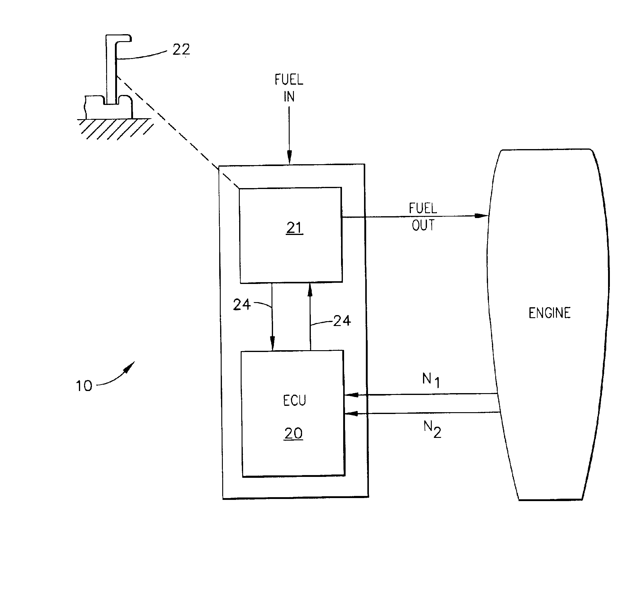
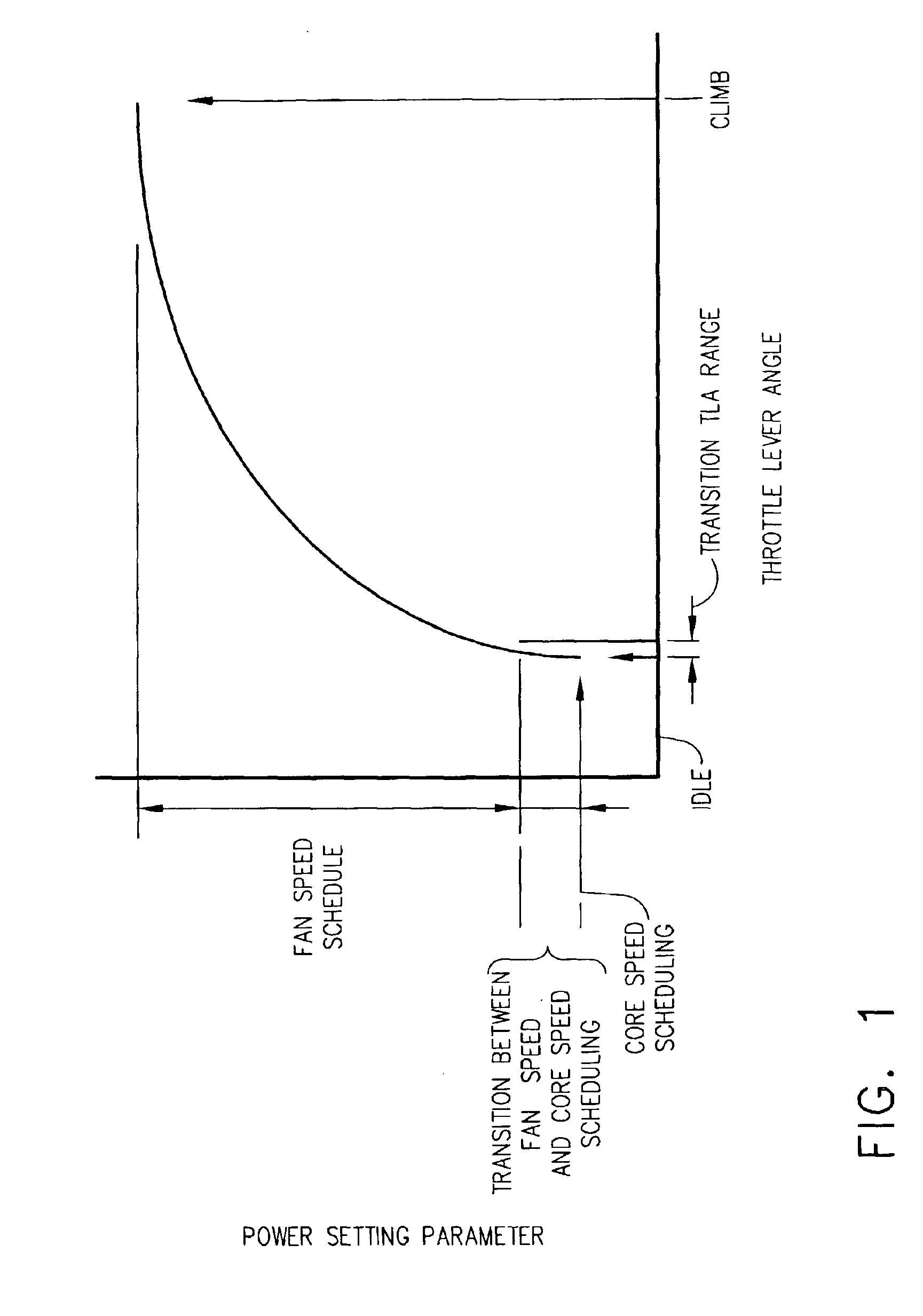
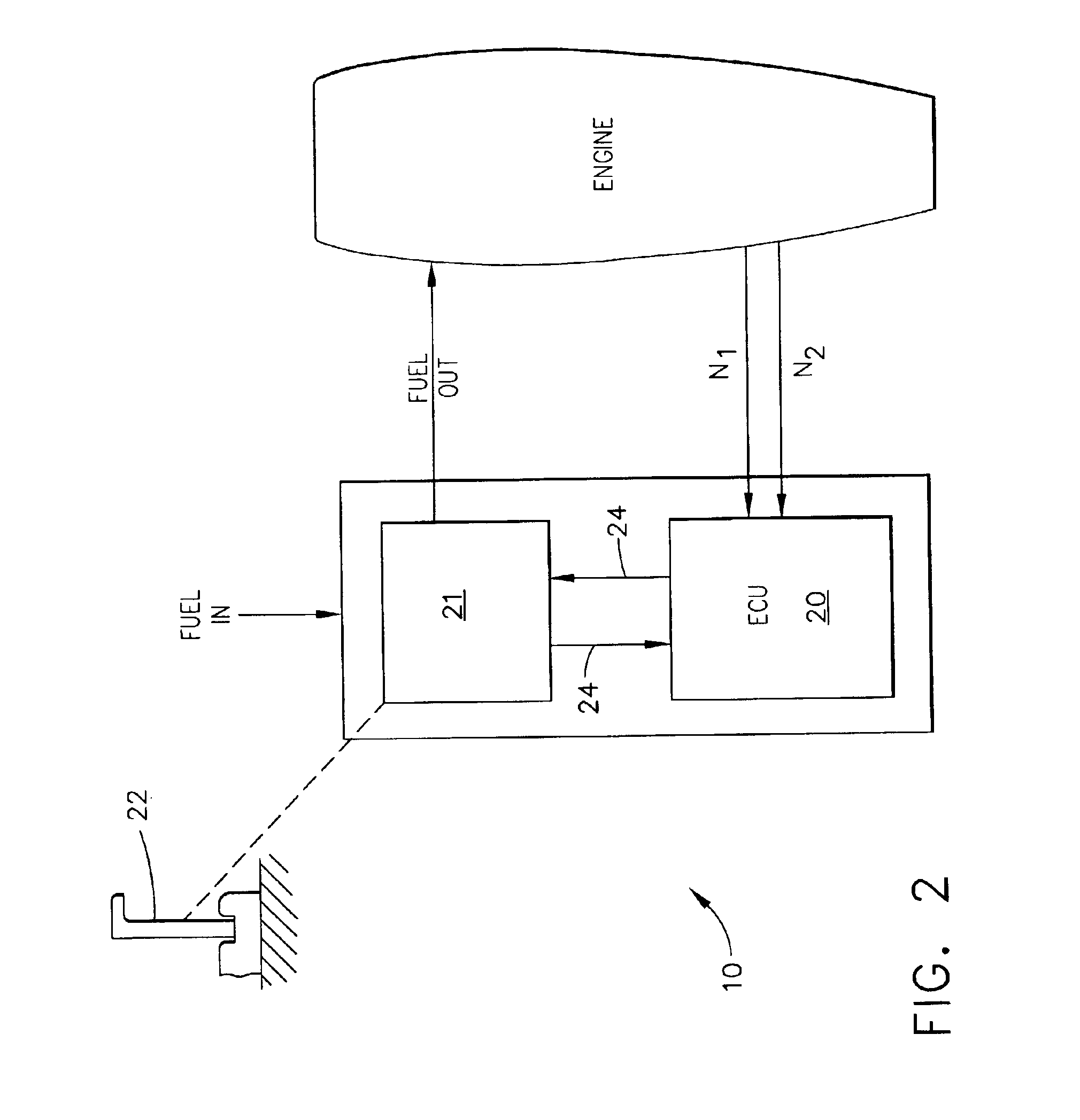
[0019]Referring now to the drawings in detail, and particularly FIG. 1, the desired power setting behavior versus throttle lever angle (TLA) is depicted. For the majority of the throttle lever angle (TLA) range, the fan speed of the turbofan engine is the controlling parameter. At idle, the control parameter is the core speed of the turbofan engine. As indicated, there is to be a small region where a transition between fan speed and core speed control occurs; but all dead bands are eliminated by controlling fuel flow to the engine under the following protocol:

[0020]The change in fan speed for a fuel flow change is called the fuel flow gain for f...


PUM


Abstract

A method for selecting a setpoint for a turbofan engine having a fan speed and a core idle speed scheduling includes determining a weighting factor based upon a throttle lever position, the weighting factor being zero in an idle region and ranging from zero to one in a dead band region and applying the weighting factor to an output of a fan speed governor and to an output of a core speed governor to select the setpoint.

Description

RELATED APPLICATIONS[0001]This application is a continuation in part of application Ser. No. 10 / 027,575 filed on Dec. 19, 2001, now U.S. Pat. No. 6,688,097.BACKGROUND OF THE INVENTION[0002]This invention relates to a throttle control for an aircraft turbofan engine, and more particularly to a throttle control, which eliminates dead band in the throttle control.[0003]Typically, two different power setting parameters are used to define the speed of operation of a turbofan engine. These are fan speed at high power setting and engine core speed at idle. Historically, the transition to fan speed from core speed causes a dead band or slippage in the throttle response. The dead band is different for each engine due to the variation in engine hardware and control sensors.[0004]The disclosure in U.S. Pat. No. 4,296,601 seeks to address this problem by controlling to a combined engine speed parameter. The combined speed parameter is comprised of core speed and fan speed. The combined paramete...

Claims


Application Information

Patent Timeline
Patent Type & Authority Patents(United States)
IPC IPC(8): F02C9/28F02C9/00
CPCF02C9/28F05D2220/36F05D2270/304
Inventor CHAPMAN, GREGORY J.RUSHINSKY, JOHN J.
Owner HONEYWELL INT INC
Learn More