Proportional fuel pressure amplitude control in gas turbine engines

a gas turbine engine and proportional technology, applied in the direction of engines/engines, engine starters, turbine/propulsion engine ignition, etc., can solve the problems of change in pressure drop across the valve, and achieve the effect of increasing pressure drop, reducing flow, and increasing fuel flow

Inactive Publication Date: 2009-11-12
DELAVAN
View PDF17 Cites 7 Cited by
  • Summary
  • Abstract
  • Description
  • Claims
  • Application Information

AI Technical Summary

Benefits of technology

[0024]In accordance with the invention, if combustion instability is detected, the step of adjusting the initial fuel pressure can include commanding the proportional valve portion to move toward a closed position, increasing the pressure drop thereacross, thus reducing the flow of fuel passing therethrough, and allowing a higher percentage of fuel flow to be delivered through the pulsating valve portion. The proportional valve can be adapted and configured to continue to close if instability continues to be detected and wherein the proportional valve ceases to close if instability ceases to be detected. A mean combined fuel flow rate flowing through the proportional and pulsating valve portions can be kept substantially constant, if so-desired, by adjusting respective valve portions. This can be accomplished by monitoring fuel flow rate and / or pressures and adjusting valve portions accordingly.
[0025]In accordance with the invention, if combustion instability is not detected, the step of adjusting fuel pressure can include the step of commanding the proportional valve portion to move toward an open position, decreasing pressure drop thereacross and increasing the flow of fuel passing therethrough, and reducing the proportion of fuel flowing through the pulsating valve portion. If instability is not detected, the method can further include the step of commanding the pulsating valve portion to revert to a default position. The default position can be one that allows a predetermined pressure drop thereacross and a corresponding flow rate to pass therethrough, or alternatively, which is a closed position. A mean combined fuel flow rate flowing through the proportional and pulsating valve portions can be kept substantially constant, if so-desired, as set forth above.

Problems solved by technology

The proportional valve portion is in fluid connection with the supply conduit adapted and configured to gradually open or close, thereby resulting in a change in pressure drop across the valve.

Method used


Image

  • Proportional fuel pressure amplitude control in gas turbine engines
  • Proportional fuel pressure amplitude control in gas turbine engines
  • Proportional fuel pressure amplitude control in gas turbine engines

Examples


Embodiment Construction

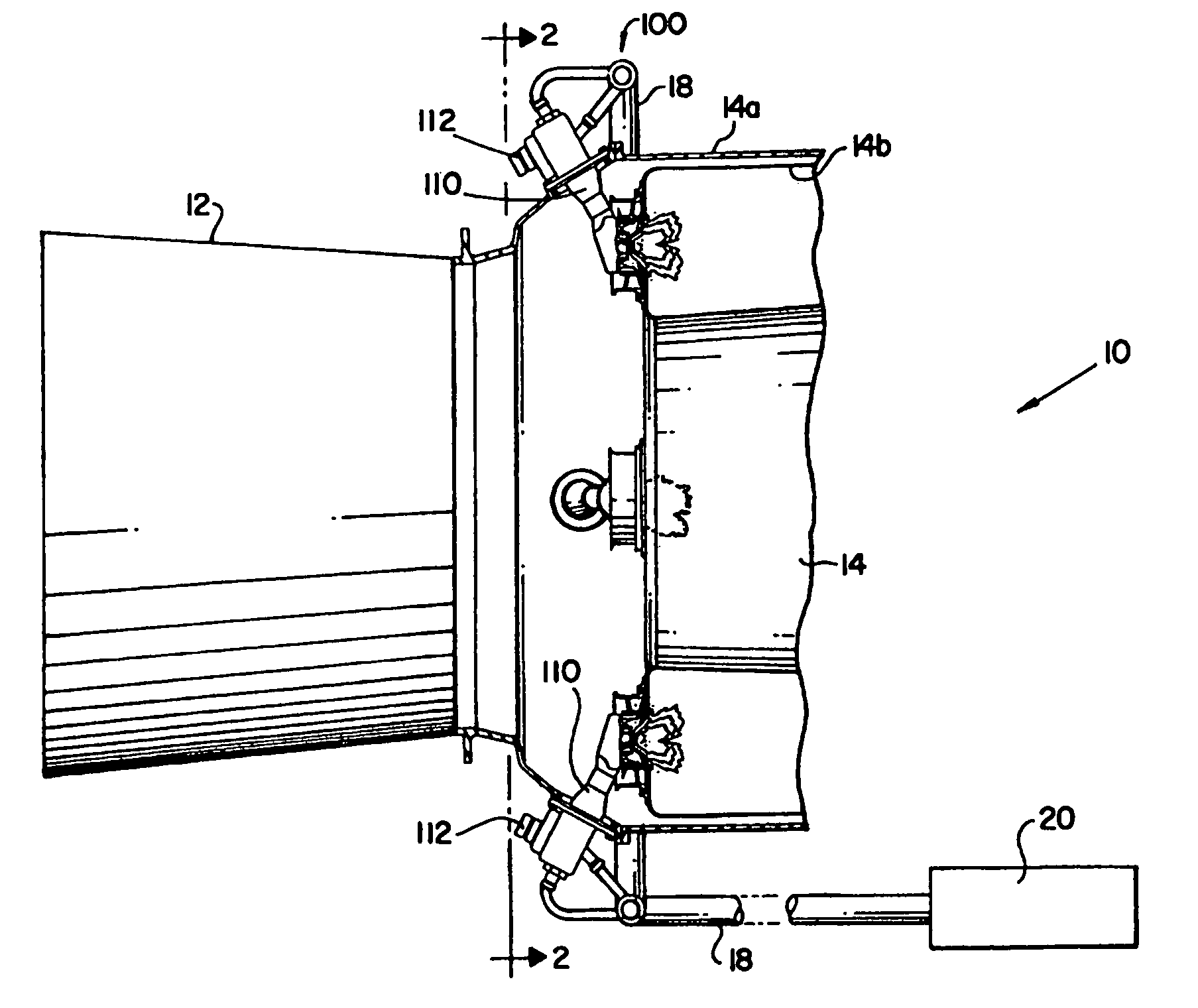
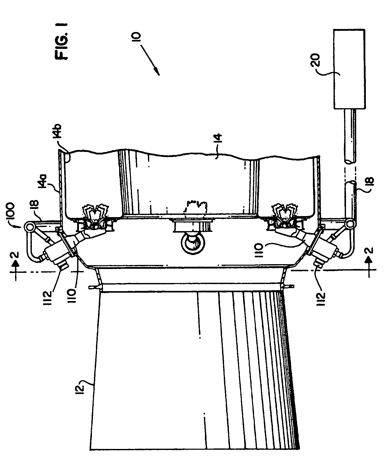
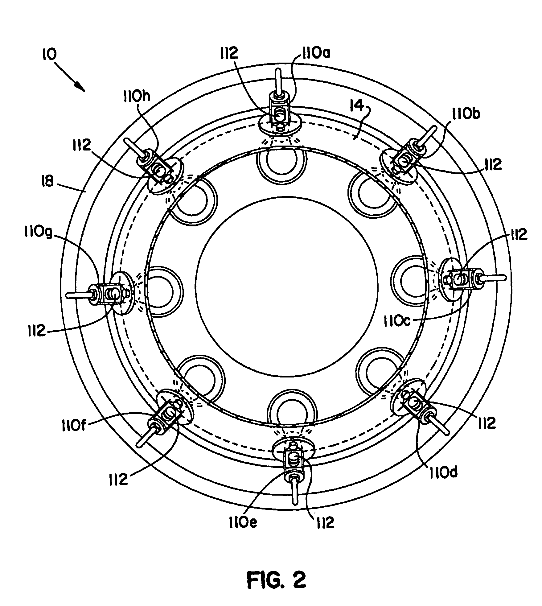
[0037]The proportional fuel pressure amplitude control valves and related methods and systems are particularly useful in conjunction with active combustion control systems, such as those described in U.S. Patent Publication Number 2007 / 0119147 to Cornwell et al., for example, which application is hereby incorporated by reference in its entirety. Preferably, such active combustion control systems are designed to reduce localized thermo-acoustic combustion instabilities within the combustion chamber of a gas turbine engine. In such instances, the valve assemblies disclosed herein can be employed to pulsate or otherwise modulate fuel flow to individual fuel injectors at extremely high frequencies in excess of about 1000 Hz in proportion to detected combustion instability, while additionally providing a capability for adjustable amplitude of fuel pressure of such fuel pulsations. The pulsating portion of valves in accordance with the present invention can be any suitable pulsating valve...


PUM


Abstract

Valve systems for controlling a flow of fuel in a gas turbine engine and related methods are provided. In one embodiment, the valve system includes a supply conduit, a proportional valve portion, and a pulsating valve portion. The supply conduit is adapted and configured for receiving and carrying a flow of fuel. The proportional valve portion is in fluid connection with the supply conduit adapted and configured to gradually adjust a pressure drop thereacross and thus a flow rate of fuel flowing therethrough. The pulsating valve portion is in fluid connection with the supply conduit, in parallel with the proportional valve portion, and is adapted and configured to rapidly adjust a pressure drop thereacross and thus a flow rate of fuel flowing therethrough.

Description

BACKGROUND[0001]1. Field of the Invention[0002]The subject invention is directed to gas turbine engines, and more particularly, to a valve system and related methods for adjusting fuel pressure delivered to fuel injectors associated with the combustor of a gas turbine engine for actively controlling the combustion process to maintain combustion stability and otherwise optimize engine performance.[0003]2. Background of the Related Art[0004]Combustion instability is a significant problem in the design of low-emission, high performing combustion chambers for gas turbines. Combustion instability is generally understood as high amplitude pressure oscillations that occur as a result of the turbulent nature of the combustion process and the large volumetric energy release within the combustion chamber. Combustion instability diminishes engine system performance, and the vibrations resulting from pressure oscillations can damage hardware components, including the combustion chamber itself. ...

Claims


Application Information

Patent Timeline
Patent Type & Authority Applications(United States)
IPC IPC(8): F02C9/26
CPCF05D2270/701F02C9/263F02C9/26F02C9/28
Inventor GOEKE, JERRY L.WILLIAMS, BRANDON P.
Owner DELAVAN
Why Eureka
Try Eureka