Fuel cell system and method for operating same

a fuel cell and system technology, applied in the direction of fuel cells, fuel cell auxiliaries, electrochemical generators, etc., can solve the problems of difficult to achieve uniform distribution of reactants through a multitude of feed channels that are in close proximity to each other, and achieve the effect of improving water management, improving pressure drop, and improving the uniformity of reactant distribution

Inactive Publication Date: 2005-07-07
BDF IP HLDG
View PDF8 Cites 23 Cited by
  • Summary
  • Abstract
  • Description
  • Claims
  • Application Information

AI Technical Summary

Benefits of technology

[0008] This recirculation of depleted reactant streams maintains or increases the total flow rate through the anode chamber and the cathode chamber for a given reactant stoichiometry. This results in a higher pressure drop across the fuel cell stack, which in turn improves the uniformity of distribution of reactants in the fuel cell stack and improves water management, when the stack is operated at less than full power. By increasing the reactant stream flow rate through the cells under these conditions, the operation of the full cell stack become more stable and the distribution of individual cell voltages within the fuel cell stack becomes more even, as does the distribution of current density within and among the individual cells. This makes it possible to enhance the overall power output of the fuel cell stack.
[0009] In addition, by recirculating wet exhaust it becomes possible to adjust the humidity of the incoming reactant stream on the anode side and / or the cathode side, and the fuel cell system can be improved.
[0010] Further, including a water separator in the system allows an improved discharge of water from the system.

Problems solved by technology

However, achieving uniform distribution of reactants through a multitude of feed channels that are in close proximity to each other can be difficult, and can be dependent on the pressures and load ranges of the system.

Method used


Image

  • Fuel cell system and method for operating same
  • Fuel cell system and method for operating same

Examples


Embodiment Construction

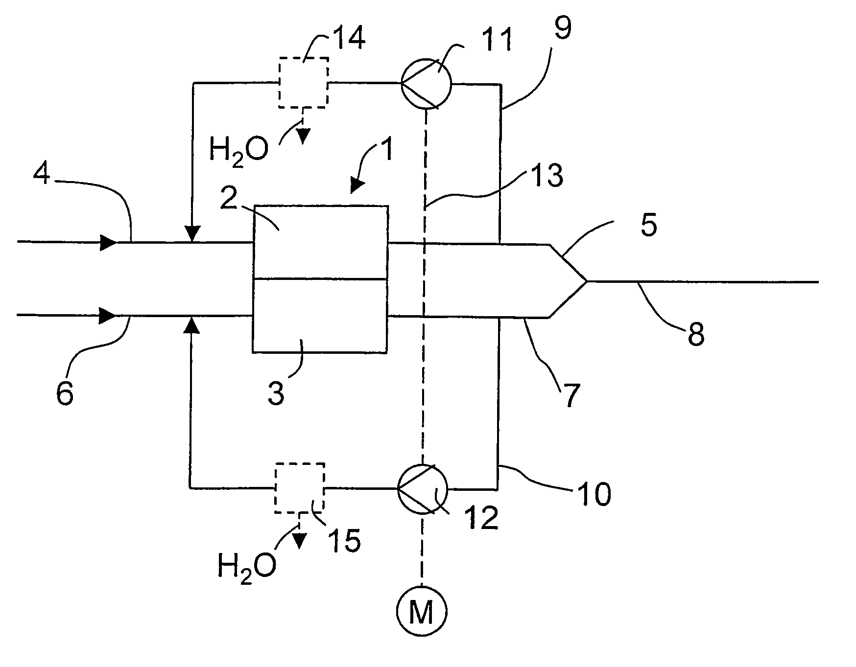
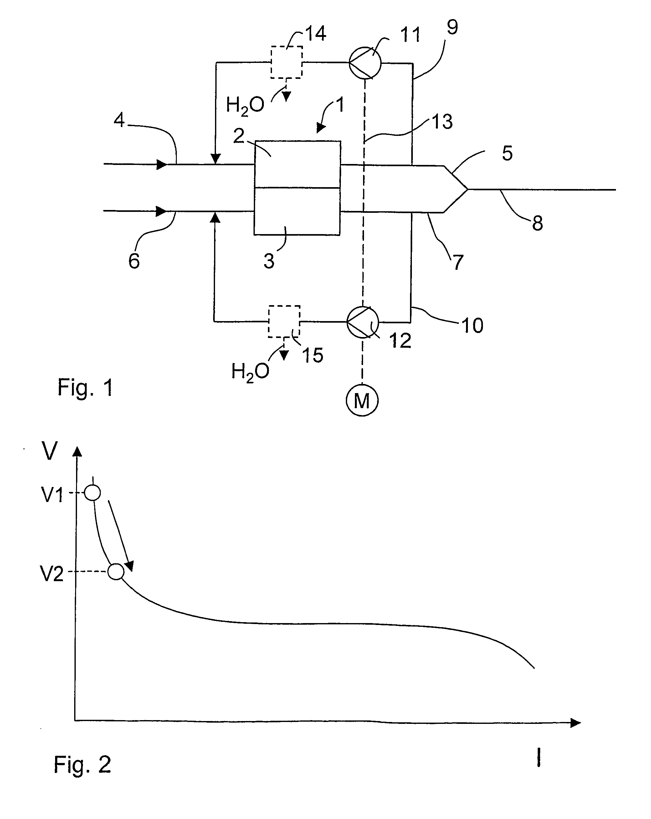
[0014]FIG. 1 shows part of one embodiment of the present fuel cell system. Fuel cell stack 1 comprises several single cells, which are arranged in a stack, whereby the individual reactant chambers are supplied with reactant streams in parallel. Accordingly, fuel cell stack 1 possesses multiple anodes, which collectively are referred to as anode 2, and multiple cathodes, which collectively are referred to as cathode 3.

[0015] A hydrogen-containing fuel stream is supplied to anode 2. The fuel stream may be, for example, pure hydrogen or a hydrogen-rich reformate stream. The fuel stream reaches anode 2 through a fuel feed line 4 connected to the anode 2. Anode exhaust is discharged from anode 2 through anode exhaust line 5. Cathode 3 is supplied with an oxidant stream, such as, for example, air or oxygen, through an oxidant feed line 6 connected to the cathode 3. Cathode exhaust is discharged from cathode 3 through cathode exhaust line 7. Anode exhaust line 5 and cathode exhaust line 7...


PUM

PropertyMeasurementUnit
currentaaaaaaaaaa
pressureaaaaaaaaaa
pressureaaaaaaaaaa

Abstract

A fuel cell system has recycle lines for recycling exhaust from the cathode and exhaust from the anode, with a recirculation device in each of the recycle lines. The recirculation devices are operated by a drive, such as a drive motor, with the drive and the two recirculation devices arranged on a common shaft.

Description

BACKGROUND OF THE INVENTION [0001] 1. Field of the Invention [0002] The invention concerns a fuel cell system and a method for operating the same. [0003] 2. Description of the Related Art [0004] Fuel cell systems typically contain fuel cell stacks that comprise a number of individual cells. The individual fuel cells and the stacks are usually supplied with reactant streams in parallel, with a hydrogen-containing fuel stream being supplied to the anode, and an oxidant stream, such as air or oxygen, being supplied to the cathode. Ideally, the reactants are essentially uniformly fed to all the individual cells, with even flow distribution. German Patent Application No. DE 199 29 472 A1 describes a fuel cell system of this type, for example. [0005] However, achieving uniform distribution of reactants through a multitude of feed channels that are in close proximity to each other can be difficult, and can be dependent on the pressures and load ranges of the system. Accordingly, there rema...

Claims


Application Information

Patent Timeline
Patent Type & Authority Applications(United States)
IPC IPC(8): H01M8/04089H01M8/04119
CPCH01M8/04097Y02E60/50H01M8/04156
Inventor KNOOP, ANDREASPEINECKE, VOLKER
Owner BDF IP HLDG
Why Eureka
Try Eureka