Robotic bridging system

a robotic bridge and bridge technology, applied in bridges, program control, instruments, etc., can solve problems such as interfering with the ability of ugv, and achieve the effect of facilitating the retention of the second elongated span and reducing the magnitude of tension

Active Publication Date: 2020-04-28
EAGLE TECH LLC
View PDF27 Cites 1 Cited by
  • Summary
  • Abstract
  • Description
  • Claims
  • Application Information

AI Technical Summary

Benefits of technology

[0012]The method further involves using a retention element disposed on the deployment support bracket to prevent a spring bias force acting on the second elongated span from causing the second elongated span to rotate about the hinge axis from the closed configuration to the open configuration. In some scenarios, the tension force which is applied to the first elongated span when in the stowed position can be used to indirectly facilitate retention of the second elongated span by the retention element.
[0013]In the method disclosed herein, the deploying process comprises pivoting the first elongated span about the first end, and concurrently releasing the second elongated span from the retention element in response to the extending. Thereafter, the travel limiting element is used to limit a maximum rotation of the second elongated span about the hinge axis relative to the first elongated span. The method can further involve setting the travel limit element in accordance with a user selectable magnitude of the obtuse angle. The deploying process further comprises continuing to pivot the first elongated span about the first end by further extending the tension element until tension is relieved on the tension element. The first end of the first elongated span is then passively released from a pivot structure disposed on the deployment support bracket. For example, this part of the process can involve automatically disconnecting the tension element from a receiver in the first elongated span by reducing a magnitude of tension applied by the tension element.

Problems solved by technology

In many instances where UGVs are utilized, they can encounter obstacles which interfere with the ability of the UGV to transit a particular area.
While these conventional solutions can be useful in some situations, they are usually only helpful for overcoming obstacles of a certain limited size or type.

Method used


Image

  • Robotic bridging system
  • Robotic bridging system
  • Robotic bridging system

Examples


Embodiment Construction

[0027]It will be readily understood that the solution described herein and illustrated in the appended figures could involve a wide variety of different configurations. Thus, the following more detailed description, as represented in the figures, is not intended to limit the scope of the present disclosure, but is merely representative of certain implementations in various different scenarios. While the various aspects are presented in the drawings, the drawings are not necessarily drawn to scale unless specifically indicated.

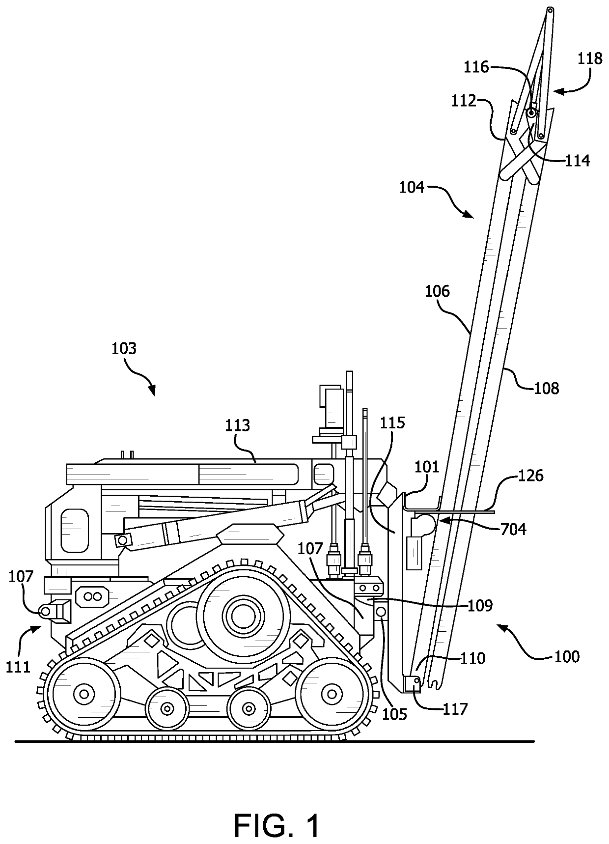
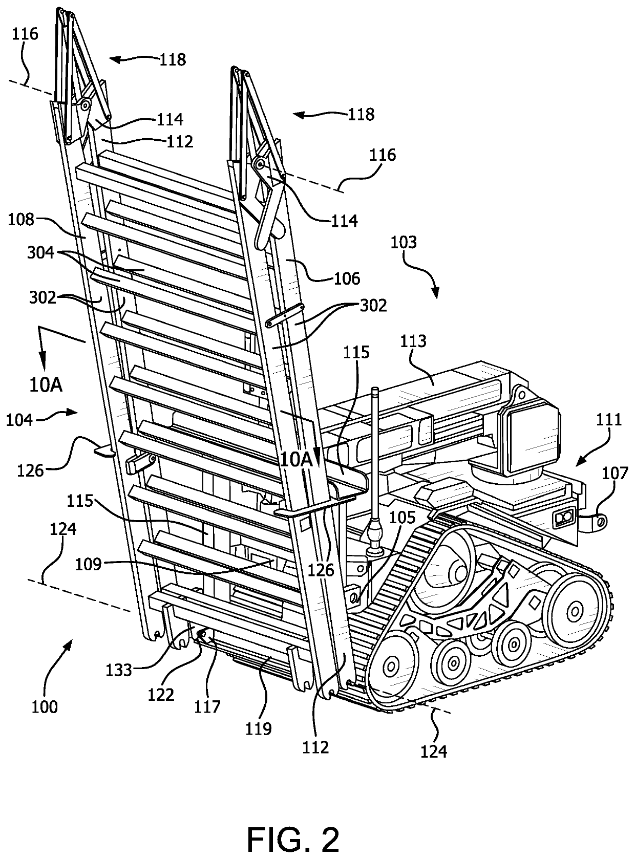
[0028]The methods and / or systems disclosed herein facilitate an improved ability for UGVs to travel over certain types of obstacles. The solution involves a robot-mounted obstacle bridging payload is flexible for handling multiple types of obstacles, can be deployed with a robot remotely, is simple, low-cost, and lightweight. The solution is configured so that it does not require a dedicated UGV bridging vehicle, but can be instead be removably mounted on any c...


PUM


Abstract

UGV bridging system includes a first end of a first elongated span of a hinged bridge structure disposed on a deployment support bracket which is secured to a UGV. A second elongated span is hingedly supported at a second end of the first elongated span opposed from the first end. A tension element applies a tension force to the first elongated span at a location intermediate the first and second ends. The tension force secures the first elongated span in a stowed position adjacent the deployment support bracket. A retention element associated with the deployment support bracket prevents the second elongated span from rotating about the hinge axis in response to a spring bias force. Deployment involves pivoting the first elongated span and concurrently releasing the second elongated span from the retention element in response to the extending.

Description

BACKGROUNDStatement of the Technical Field[0001]The technical field concerns unmanned ground vehicles, and more particularly systems for improving the ability of unmanned ground vehicles to transit obstacles.Description of the Related Art[0002]The related art concerns unmanned ground vehicles (UGVs) and more particularly systems which improve the mobility of such UGVs in the presence of certain types of obstacles. UGVs are increasingly being used in a wide variety of roles and settings. These can include domestic, military and international applications where the UGV is used to perform certain tasks which are deemed too dangerous or are otherwise inappropriate for personnel or other types of manned vehicles. Examples include explosive ordnance disposal, situations involving chemical or biological threats, handling of hazardous materials (HAZMAT), countermine operations for disabling and / or removal of mines. In other scenarios UGVs can be used to facilitate transportation of equipmen...

Claims


Application Information

Patent Timeline
Patent Type & Authority Patents(United States)
IPC IPC(8): E01D15/12E01D15/00E01D21/06B25J9/16E01D18/00E01D15/127
CPCE01D21/06E01D15/005B25J9/162E01D15/127E01D15/124G05B2219/40298E01D18/00
Inventor BOWMAN, MICHAEL E.MEEHAN, ROBERTBOSSCHER, PAUL M.
Owner EAGLE TECH LLC
Why Eureka
Try Eureka