
Power converter for led fixture

a technology of power converter and led fixture, which is applied in the direction of electrical equipment, electrical variable regulation, instruments, etc., can solve the problems of inflexible application of led driver, ineffective location, and add to the complexity and thus cost of led driver, and achieve the effect of easy assessment of supply voltag

Active Publication Date: 2020-05-19
ELDOLAB HLDG
View PDF14 Cites 0 Cited by
  • Summary
  • Abstract
  • Description
  • Claims
  • Application Information

AI Technical Summary

Benefits of technology

The present invention provides an LED driver that can easily assess the characteristics of the supply voltage. The measured electrical characteristic, such as voltage, current, frequency, and frequency content, is used to determine the electrical characteristic of the supply voltage. This information enables increased functionality in controlling and powering the LED lights, and may cause changes in behavior of the driver when the supply is externally switched.

Problems solved by technology

This would however render the application of the LED driver rather inflexible and maybe ineffective on locations where another type of supply voltage is provided.
Such solutions however add to the complexity and thus costs of the LED driver.

Method used


Image

  • Power converter for led fixture
  • Power converter for led fixture
  • Power converter for led fixture

Examples


Embodiment Construction

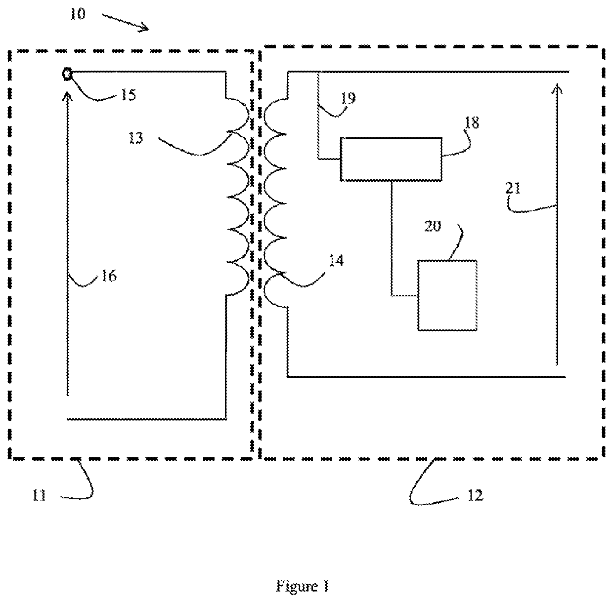
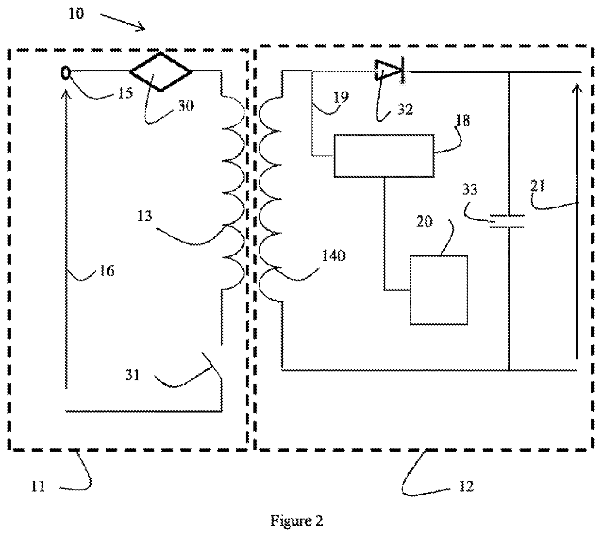
[0034]FIG. 1 depicts an embodiment of a power converter according to the present invention. FIG. 1 schematically depicts a power converter 10 comprising a power converter having a primary circuit 11 and a secondary circuit 12, comprising a primary 13 respectively secondary winding 14 that are magnetically coupled (thus forming a transformer 13,14). Optionally, the primary circuit and the secondary circuit are galvanically separated. The primary circuit 11 further comprises an input terminal 15 for receiving a supply voltage 16, e.g. an AC mains voltage. The secondary circuit 12 as shown further comprises a sensor 18 for sensing an electrical characteristic of the secondary circuit 12. In the embodiment as shown, the sensor 180 is arranged to determine an electrical characteristic of the secondary winding 14 of the secondary circuit 12 (as schematically indicated by the line 19). As an example, the sensor 18 can be arranged to measure the voltage over the secondary winding 14 or the ...


PUM


Abstract

A power converter for supplying an output voltage or an output current for powering an LED fixture is described, the power converter comprising:a primary circuit comprising:an input terminal for receiving a supply voltage;a primary winding connected to the input terminal;a secondary circuit comprising a secondary winding that is magnetically coupled with the primary winding for providing the output voltage or output current;the power converter further comprising:a sensor for measuring an electrical characteristic of the secondary circuit and;a detector configured to determine an electrical characteristic of the supply voltage based on the measured electrical characteristic of the secondary circuit.

Description

FIELD OF THE INVENTION[0001]The invention relates to the field of LED drivers, and more specifically to power converters, such as flyback converters, as applied in such LED drivers.BACKGROUND OF THE INVENTION[0002]LED drivers are widely used for powering various types of LED fixtures, including one or more LEDs. Typically, such an LED driver converts a supply voltage to an output voltage (typically a DC voltage) or output current for powering the LEDs of the LED fixture. In general, an LED driver is adapted to accommodate different types of supply voltages, such that it can be applied on different locations, e.g. where different types of supply voltages (e.g. different types of mains voltages) are used.[0003]As an example, an LED driver can be adapted to be supplied with either a 230V, 50 Hz or a 277V, 60 Hz supply voltage. Further, an LED driver typically comprises a galvanic separation between the supply side (receiving the supply voltage) and the load side, where the LED fixture ...

Claims


Application Information

Patent Timeline
Patent Type & Authority Patents(United States)
IPC IPC(8): H05B45/37H02M3/335H05B45/385H05B33/08H05B44/00
CPCH05B45/37H02M3/33507H02M3/335H05B45/385
Inventor SAES, MARCVERBEEK, WILLEM JOHANNES MARIA
Owner ELDOLAB HLDG
Learn More