Check patentability & draft patents in minutes with Patsnap Eureka AI!

Thermal transpiration generator system

a generator system and transpiration technology, applied in the direction of machines/engines, mechanical equipment, light and heating equipment, etc., can solve the problems of noisy gasoline and steam generators, unfavorable exhaust gas generation, and high operating costs, and achieve the effect of improving electrical outpu

Active Publication Date: 2020-05-26
ENG MFG CONTRACTORS
View PDF10 Cites 0 Cited by
  • Summary
  • Abstract
  • Description
  • Claims
  • Application Information

AI Technical Summary

Benefits of technology

The present invention provides a thermal transpiration generator system that addresses various issues of related art. The system includes a vacuum-sealed container with a rotatable shaft and a set of vanes located inside the container. The vanes are secured to the shaft for rotation therewith. The system also includes a first receiving lens and a second receiving lens for focusing energy on the light absorbing sides of the vanes. An electric generator is operatively coupled to the rotatable shaft for driving the system. The system also includes a light energy collector system that concentrates energy on the first and second receiving lenses. The system can be mounted in a vertical or horizontal orientation. Cooling bands and a cooling fan can be used to cool the interior of the system. The invention provides a significant advance in the technology and art of thermal transpiration generator systems and methods.

Problems solved by technology

Currently, electric generators typically require fuels that render them expensive to operate.
Some gasoline and steam powered generators are also noisy and can generate undesirable exhaust gases.
Additionally, the generators that require gasoline or other carbon-based fuels have undesirable time restrictions and output limitations.
Batteries can be used as back-ups but the electric generators still only operate under a limited time due to battery life, and usually are limited in overall capacity.
However, current solar powered generators require an extensive amount of area for solar panels to obtain desired power output levels and are quite expensive.
While these generators have shown that they are capable of generating some electricity in a laboratory environment, they have yet to produce desired levels of electricity with compact systems.

Method used


Image

  • Thermal transpiration generator system
  • Thermal transpiration generator system
  • Thermal transpiration generator system

Examples


Embodiment Construction

[0046]It will be apparent to those skilled in the art, that is, to those who have knowledge or experience in this area of technology, that many uses and design variations are possible for the thermal transpiration systems disclosed herein. The following detailed discussion of various alternative and preferred embodiments will illustrate the general principles of the invention. However, other embodiments suitable for other applications will be apparent to those skilled in the art given the benefit of this disclosure.

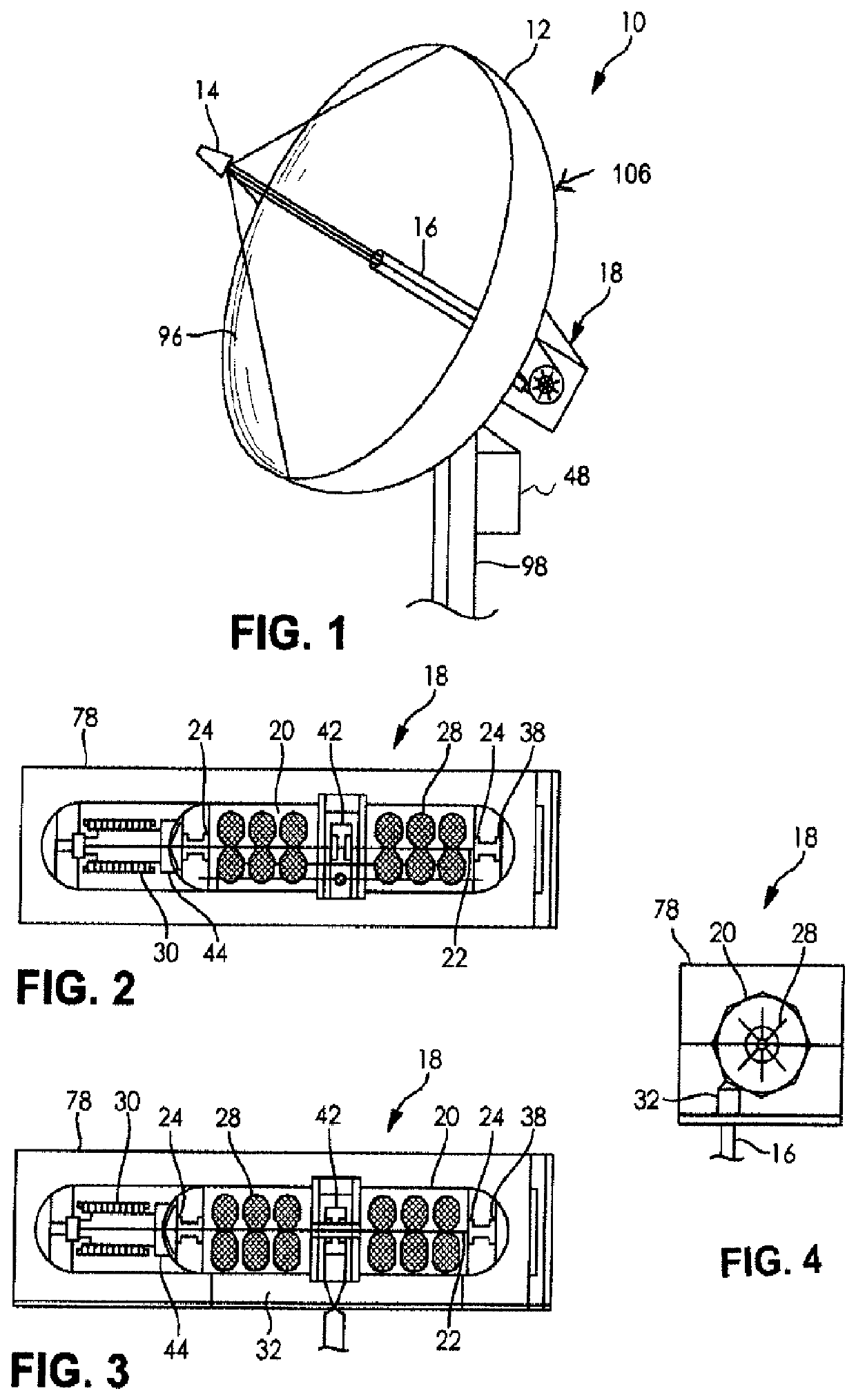
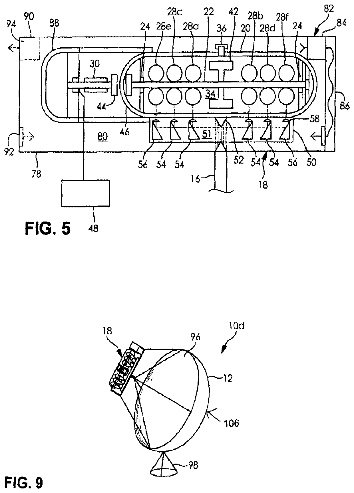
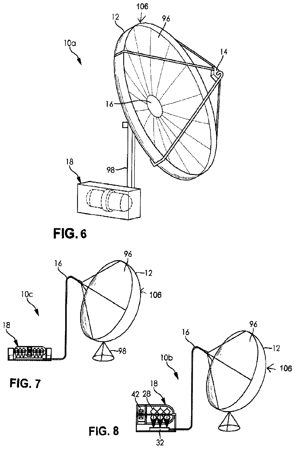
[0047]Referring now to the drawings, FIGS. 1 to 5 show a thermal transpiration generator system 10 according to a first embodiment of the present invention. The illustrated thermal transpiration generator system 10 includes a parabolic dish 12, a secondary reflector 14 receiving solar energy from the parabolic dish 12, and a carrier tube 16 directing solar energy from the parabolic dish 12 to a thermal transpiration device or generator 18. The illustrated thermal transpir...


PUM


Abstract

A system includes a thermal transpiration generator having a vacuum-sealed container, a rotatable shaft within the container, bearings supporting the shaft within the container, a first set of vanes secured to the shaft, a second set of vanes secured to the shaft, a first receiving lens for focusing energy on the first set of vanes, a second receiving lens for focusing energy on the second set of vanes, and a flywheel secured to the shaft. An electric generator is located outside the container and is coupled to the rotatable shaft with a magnetic coupler to be driven by rotation of the shaft. The system further includes a light energy collector system concentrating energy on each of the first and second receiving lenses, and an outer housing located about the container and the electric generator.

Description

FIELD OF THE INVENTION[0001]The field of the present invention generally relates to power generation systems and, more particularly, to power generation systems using solar energy to generate electricity.BACKGROUND OF THE INVENTION[0002]Currently, electric generators typically require fuels that render them expensive to operate. Some gasoline and steam powered generators are also noisy and can generate undesirable exhaust gases. Additionally, the generators that require gasoline or other carbon-based fuels have undesirable time restrictions and output limitations. Batteries can be used as back-ups but the electric generators still only operate under a limited time due to battery life, and usually are limited in overall capacity. As a result alternative energy powered generators such as solar powered generators have been developed. However, current solar powered generators require an extensive amount of area for solar panels to obtain desired power output levels and are quite expensi...

Claims


Application Information

Patent Timeline
Patent Type & Authority Patents(United States)
IPC IPC(8): F03G6/04F03G6/06F03G7/00F24S23/71F24S23/30F24S23/79F24S30/425
CPCF03G7/00F03G6/04F03G6/06F24S30/425Y02E10/46F24S23/71F24S23/79F24S23/30F03G7/016
Inventor NUTTER, MARK EUGENE
Owner ENG MFG CONTRACTORS
Features
  • R&D
  • Intellectual Property
  • Life Sciences
  • Materials
  • Tech Scout
  • Unparalleled Data Quality
  • Higher Quality Content
  • 60% Fewer Hallucinations
Learn More