Motor with stiffened stator core, manufacturing method thereof, and washing machine including the motor
a technology of stator core and manufacturing method, which is applied in the direction of stator/rotor body manufacturing, magnetic circuit shape/form/construction, magnetic circuit rotating parts, etc., can solve the problems of not being able to simultaneously wind a plurality of phase coils and the blocking unit is not fixed to the teeth, and achieves low profile
- Summary
- Abstract
- Description
- Claims
- Application Information
AI Technical Summary
Benefits of technology
Problems solved by technology
Method used
Image

Examples
first embodiment
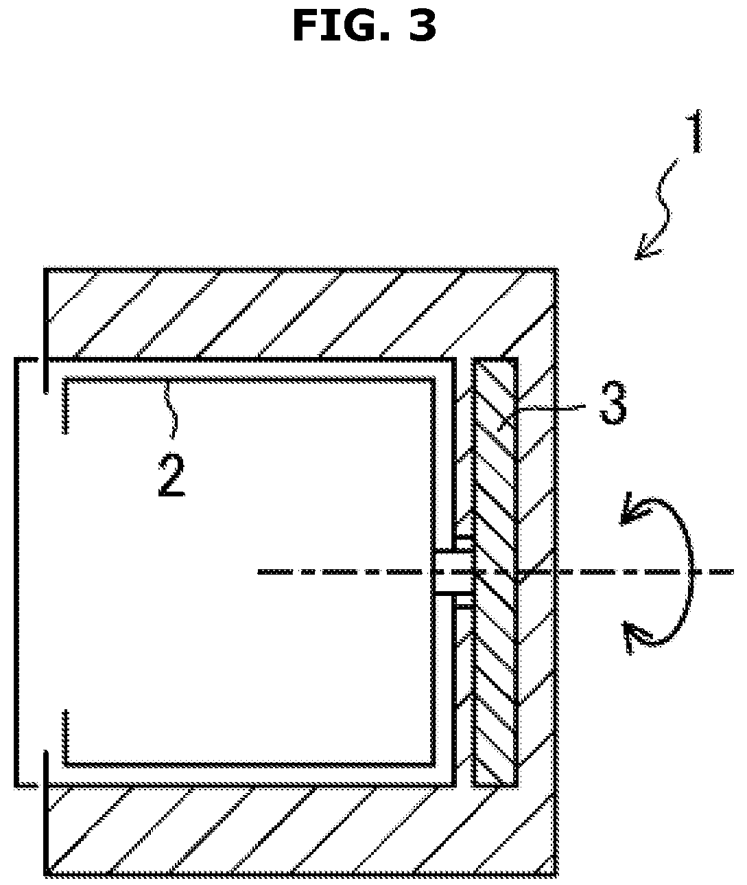
[0110]In a first embodiment, a method of improving a stiffness of the stator 20 disposed at the DD motor 3 will be mainly described. FIGS. 4 to 8 schematically illustrate a method of manufacturing the stator 20.
[0111]First, as illustrated in FIG. 4(a), a band-shaped divided core 5 including a yoke core 5a and a plurality of teeth cores 5b is prepared. The band-shaped divided core 5 is formed by blanking steel plates in forms illustrated in (a) of FIG. 4 and stacking the blanked pieces as illustrated in FIG. 4(b).
[0112]However, the yoke core 5a includes groove portions 7 formed between the teeth cores 5b adjacent to each other. A shape of the groove portions 7 is not particularly limited, but the groove portions 7 may be, for example, formed in a V-shape.
[0113]Next, as illustrated in FIG. 5(a), the band-shaped divided core 5 is bent in an arc shape by having the plurality of teeth cores 5b placed inward. Here, the band-shaped divided core 5 is bent in the arc shape due to opened port...
second embodiment
[0161]In a motor of the second embodiment, a method of improving flame resistance or durability, manufacturability of a stator will be mostly described.
Overview of a Motor in the Second Embodiment
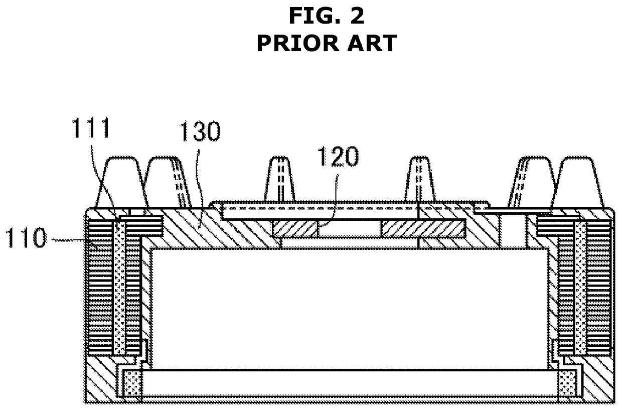
[0162]When a sub-core is mounted on a main core as in the above-mentioned Patent Document 2, the flame resistance is excellent since a leakage of flame may be blocked even when a coil ignites. However, an effect of suppressing vibrations (particularly, axial vibrations) of front ends of teeth cannot be obtained since gaps between the front ends of the teeth are not fixed to blocking units.
[0163]When the gaps between the front ends of the teeth are fixed as in Patent Document 3 or Patent Document 4, the vibrations of the front ends of the teeth may be suppressed such that a low noise may be promoted.
[0164]However, a difficulty exists in terms of durability since the gaps between the front ends of the teeth are fixed by adhering, and the like in Patent Document 3 or Patent Document 4, and a d...
third embodiment
[0222]In the motor of the third embodiment, a structure of a connection line of a coil will be mainly described.
Overview of the Motor of the Third Embodiment
[0223]The stators of the above-mentioned Patent Document 5 and Patent Document 6 both have coils of each phase separately formed. That is, after first-phase coils are completely formed, all of second-phase coils and all of third-phase coils are sequentially formed.
[0224]In this case, since a coil work has to be repeated for three times, a number of processes increases and the manufacturability decreases.
[0225]Here, the motor of the third embodiment has a structure that is capable of forming coils of each of the phases with a small number of processes and making the motor lower in profile.
[0226]A stator of the motor of the third embodiment includes a cylindrical yoke part and a plurality of teeth parts radially extending from the yoke part in equal intervals in the circumferential direction. First-phase to third-phase coil groups...
PUM
 Abstract
Description
Claims
Application Information
 - R&D
- Intellectual Property
- Life Sciences
- Materials
- Tech Scout
- Unparalleled Data Quality
- Higher Quality Content
- 60% Fewer Hallucinations
Browse by: Latest US Patents, China's latest patents, Technical Efficacy Thesaurus, Application Domain, Technology Topic, Popular Technical Reports.
© 2025 PatSnap. All rights reserved.Legal|Privacy policy|Modern Slavery Act Transparency Statement|Sitemap|About US| Contact US: help@patsnap.com