System and method for proactive traffic restoration in a network

a traffic restoration and network technology, applied in the field of system and method for proactive traffic restoration in a network, can solve the problems of insufficient real-time view of the current situation inability to provide proactive actions, and prone to deficiencies of the traffic restoration mechanism used in the network, so as to avoid service disruptions

Active Publication Date: 2020-06-02
ADVA OPTICAL NETWORKING SE
View PDF16 Cites 4 Cited by
  • Summary
  • Abstract
  • Description
  • Claims
  • Application Information

AI Technical Summary

Benefits of technology

[0011]An advantage of the system according to the first aspect of the present invention resides in the fact that the network traffic restoration can take place before a failure actually occurs. Consequently, service disruptions are avoided. Conventional systems are in general based on threshold-based operating points for link failure prediction (for instance if link L2 fails then link L1 will fail etc.). In contrast, the system according to the first aspect of the present invention follows a model-driven approach being not constrained to predefined rules. Whereas a conventional system namely triggers a prevention when a certain failure has already occurred (reactive approach) the system according to the first aspect of the present invention does proactively forecast failures and does take appropriate restoration actions. In some conventional systems packets might be partially propagated to a back-up path together with a working route whereas the system according to the present invention can cater a physical layer traffic split. In contrast to conventional systems which operate mainly on periodic update of historical threshold settings, the system according to the present invention operates based on raw data. The system according to the present invention follows a model-driven forecasting framework which may be scalable for years for both restoration and new service configuration. In particular, the system according to the present invention can model traffic and forecasts in real time, considering instantaneous network states. Whereas a conventional system may only cater slow changes in quality metrics, the system according to the present invention does allow to cater for any rate of metric evolution due to intrinsic forecasting information. Conventional systems are mostly used to perform a restoration of a network. In contrast, the system according to the present invention does address both network recovery (i.e. restoration and protection) but also new service configuration. A conventional system is normally only able to enable restoration when a certain threshold is met. In contrast the system according to the present invention allows restoration well within the failure limit. Whereas a conventional system is restricted to restoration based on backup path restoration time, the system according to the present invention does not only allow for restoration based on signal quality but can also determine path quality for a global optimization. A conventional system requires typically indexing and maintenance of backup path restoration times to enable an error prediction. In contrast, the system according to the present invention bases its forecast entirely on data using real time model identification. A conventional system may be constrained to a unique quality metric such as bit error rate, BER. The system according to the present invention does not have such limitations and allows both use of uni-variate and multi-variate metrics such as bit error rate, BER, OSNR, power, attenuation, etc.

Problems solved by technology

The conventional traffic restoration mechanism used in a network is prone to deficiencies.
The conventional traffic restoration mechanism does not provide a sufficient real-time view on the current situation and does not provide proactive actions on traffic and link states.
Due to the reactive restoration approach taken by conventional networks, service disruptions may occur.
A further disadvantage of conventional traffic restoration mechanisms used in networks is that a progressive worsening condition of a working signal path in the network remains unaccounted for.
In general, the reactive traffic restoration approach used in conventional networks leads to a pessimistic system or network design resulting in a worst-case operation to meet the service level agreements SLAs.
Moreover, the conventional reactive traffic restoration approach provides very limited global optimization possibilities.

Method used


Image

  • System and method for proactive traffic restoration in a network
  • System and method for proactive traffic restoration in a network
  • System and method for proactive traffic restoration in a network

Examples


Embodiment Construction

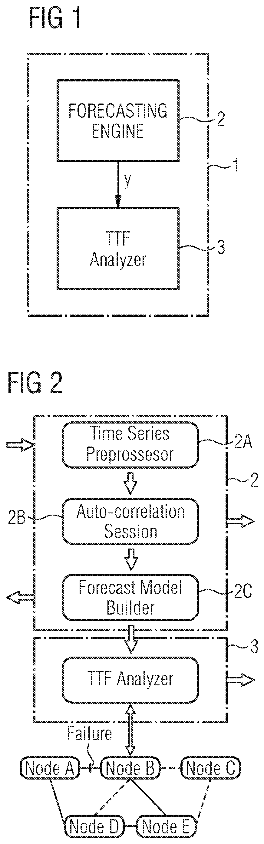
[0047]As can be seen in the block diagram of FIG. 1, the system 1 for proactive traffic restoration in a network according to the first aspect of the present invention comprises in the illustrated embodiment two main components. The system 1 comprises at least one forecasting engine 2 adapted to model and forecast traffic patterns of at least one traffic channel along a signal path of the network to provide forecast traffic quality metrics y which are supplied to a time-to-failure, TTF, analyzer 3 of the system 1 as shown in FIG. 1. The time-to-failure, TTF, analyzer 3 is configured to calculate a time-to-failure, TTF, forecast for the traffic channel based on the received forecast traffic quality metrics y. The calculated time-to-failure, TTF, forecast is evaluated in a possible embodiment to trigger a proactive network traffic restoration.

[0048]The forecasting engine 2 comprises in a possible embodiment an interface to receive historical observations of traffic parameters of at le...


PUM


Abstract

A system for proactive traffic restoration in a network includes at least one forecasting engine that models and forecasts traffic patterns of at least one traffic channel along a signal path of the network to provide forecast traffic quality metrics, y. The system further includes at least one time-to-failure, TTF, analyzer that calculates a time-to-failure, TTF, forecast for the traffic channel based on the forecast traffic quality metrics, y. The calculated time-to-failure, TTF, forecast is evaluated to trigger a proactive network traffic restoration.

Description

PRIORITY CLAIM[0001]This application claims the benefit of European Patent Application No. 17187977.8, filed Aug. 25, 2017, the disclosure of which is incorporated herein by reference in its entirety.FIELD OF THE INVENTION[0002]The invention relates to a system and method for proactive traffic restoration in a network, in particular in an optical network.TECHNICAL BACKGROUND[0003]Networks comprise network nodes connected to each other via links. In optical networks, signals are transported through optical fibers on one or more carriers at the same or different frequencies. The optical fibers form links between nodes of the optical network. A traffic channel can comprise one or more carriers transporting data from a source node of the optical network to a destination node of the optical network. Within the traffic channel, an optical signal is transported along a signal path from the source node to the destination node. A signal path can comprise a series of optical links. Networks a...

Claims


Application Information

Patent Timeline
Patent Type & Authority Patents(United States)
IPC IPC(8): H04L12/721H04L12/703H04L12/803H04L12/729H04L12/26H04L12/24H04L12/801H04L45/125H04L45/28
CPCH04L41/064H04L41/0663H04L45/28H04L45/123H04L43/0817H04L45/125H04L45/124H04L43/062H04L47/127H04L41/147H04L41/142H04L47/125H04L43/0847H04L41/5038H04L41/40H04L43/20H04L43/55
Inventor RAFIQUE, DANISHELBERS, JOERG-PETER
Owner ADVA OPTICAL NETWORKING SE
Why Eureka
Try Eureka