Optical access system and ranging method for optical access system

a technology of optical access system and optical access system, which is applied in the direction of transmission monitoring, multiplex communication, star/tree network, etc., can solve the problems of inability to guarantee the reliability of the upstream communication of the other onus, inability to disrupt the service, and inability to guarantee the upstream communication reliability of the onus #b>2, so as to prevent the disruption of services and low cost

Inactive Publication Date: 2011-02-01
OKI ELECTRIC IND CO LTD
View PDF0 Cites 4 Cited by
  • Summary
  • Abstract
  • Description
  • Claims
  • Application Information

AI Technical Summary

Benefits of technology

[0023]The present invention provides a low-cost optical access system that can continue services during the ranging window with simple controls and at a low cost.
[0027]According to the above-mentioned aspects, the working (actually-used) system transmission line is used for the downstream communication (communication from the station side to the terminal interface side) and the auxiliary system transmission line is used for the upstream communication (communication from the terminal interface side to the station side) during ranging. Here, because the station unit performs time-divided multiplexing for the downstream communication, there is no possibility of causing collision of signals. Further, the auxiliary system transmission line is used for the ranging signals, i.e., the first and second ranging signals, there is also no possibility that they collide with signals transmitted from other access terminals. Therefore, the invention can prevent the disruption of services during a ranging window at low cost without involving complicated control.

Problems solved by technology

It is because reliability of the upstream signal of the other ONUs cannot be guaranteed since the upstream communication of the ranging signal is carried out even though its delay time (see FIG. 4) is not specified, and there is a possibility that the ranging signal collides with the upstream signal of the other ONUs.
In this case, it is unable to guarantee the reliability of the upstream communication of the ONU #2 as described above.
However, it is not desirable to disrupt the service of the ONU for the ranging from a point of view of assuring quality and reliability of the service.
However, the method of using the buffer leads to an increase of cost of the PON since the required buffer capacity is large.

Method used


Image

  • Optical access system and ranging method for optical access system
  • Optical access system and ranging method for optical access system
  • Optical access system and ranging method for optical access system

Examples


Embodiment Construction

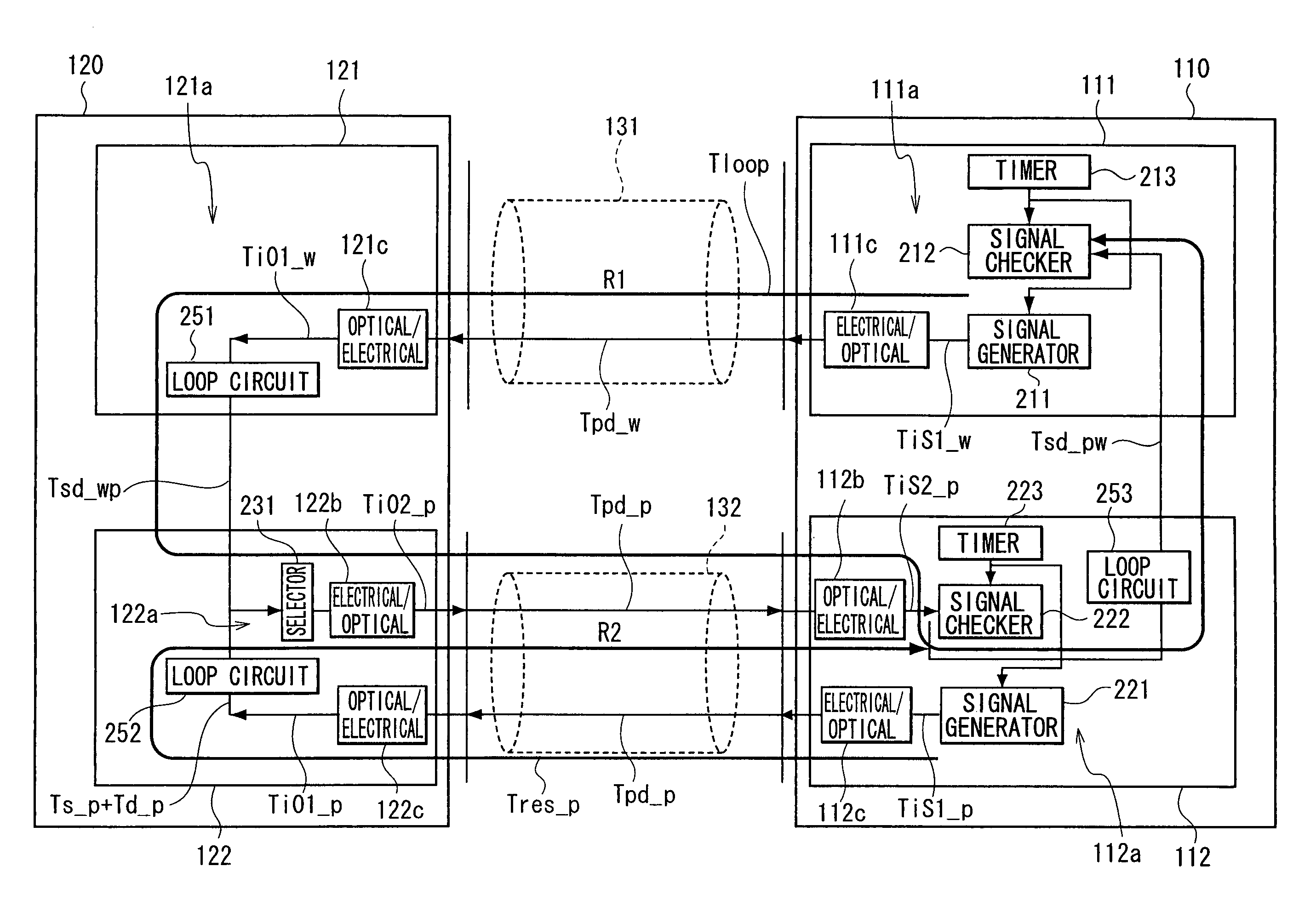
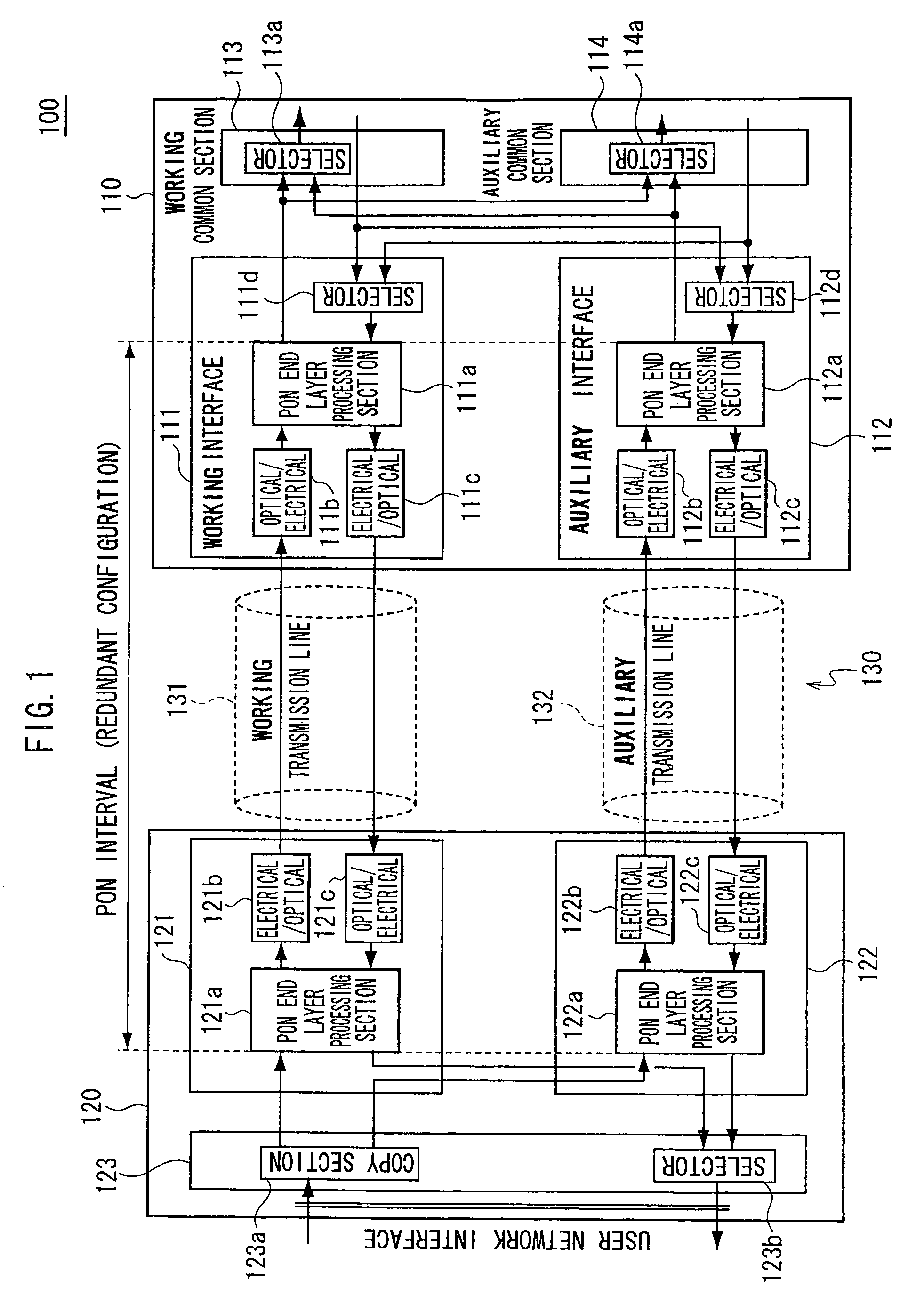
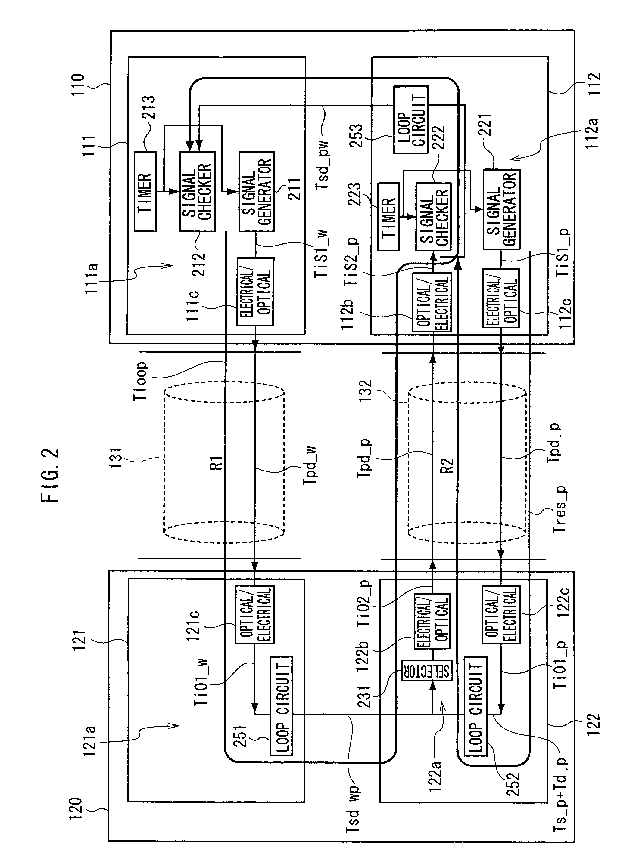
[0038]An embodiment of an optical access system of the invention will be explained below by exemplifying a case when the invention is applied to a PON system and by using FIGS. 1 and 2. It is noted that size, shape and disposition of each component are schematically shown only to a degree of helping to understand the invention and numerical conditions explained below are merely examples.

[0039]FIG. 1 is block diagram schematically showing a redundant configuration of a PON system of the embodiment. As shown in FIG. 1, the PON system 100 of the embodiment includes an OLT 110, an ONU 120 and an optical communication cable 130.

[0040]The OLT 110 includes a working system interface 111 and an auxiliary system interface 112, a working system common section 113 and an auxiliary system common section 114.

[0041]The working system interface 111 communicates with a working system interface 121 of the ONU 120 via a working system transmission line 131 (described later). The working system interf...


PUM


Abstract

A ranging signal R1 generated by a signal generator and reaches to a signal checker via a working system transmission line, a loop circuit, and an auxiliary system transmission line. The signal checker measures a delay time from the generation to the arrival of the signal R1. A ranging signal R2 generated by the signal generator and reaches to a signal checker via an auxiliary system transmission line, a loop circuit, and an auxiliary system transmission line. The signal checker measures a delay time from the generation to the arrival of the signal R12. A delay time of the working system transmission line is calculated from the delay times of the signals R1 and R2. Disruption of the services provided by the other ONUs can be prevented since the working system transmission line is not used for upstream communication of the ranging signals R1 and R2.

Description

CROSS-REFERENCE TO RELATED APPLICATION[0001]This application claims priority under 35 USC 119 from Japanese Patent Application No. 2007-119582, the disclosure of which is incorporated by reference herein.BACKGROUND OF THE INVENTION[0002]1. Field of the Invention[0003]The present invention relates to an improvement of a ranging function provided in a redundant optical access system. The invention is applicable to a redundant optical access system for constructing an access system such as a PON (Passive Optical Network) and the like.[0004]2. Description of the Related Art[0005]Hitherto, FTTx (Fiber To The x) has been known as an optical access network for providing communication services such as Internet, IP (Internet Protocol) telephone, distribution of video and the like. As the FTTx, there have been known FTTH (Fiber To The Home), FTTC (Fiber To The Curb), FTTN (Fiber To The Node), FTTP (Fiber To The Premises) and the like for example.[0006]The PON is also known as a subscriber acc...

Claims


Application Information

Patent Timeline
Patent Type & Authority Patents(United States)
IPC IPC(8): H04B10/00H04L12/44
CPCH04J3/0682H04J3/1694H04Q11/0067H04Q2011/0079H04Q2011/0088
Inventor EGUCHI, KOHEI
Owner OKI ELECTRIC IND CO LTD
Why Eureka
Try Eureka