Continuously variable transmission

a continuously variable transmission and transmission technology, applied in fluid gearings, transportation and packaging, gearing, etc., can solve the problems of high cost, complex control system of hydraulic automatic transmission, loss of transmission capacity of hydraulic transmission, etc., and achieve wide torque change range

Active Publication Date: 2020-06-09
WEIHAI TUANZHONG TRANSMISSION CO LTD
View PDF4 Cites 2 Cited by
  • Summary
  • Abstract
  • Description
  • Claims
  • Application Information

AI Technical Summary

Benefits of technology

[0027]The present invention has the effects that: since the continuously variable transmission includes an input end planetary gear set and an output end planetary gear set, a cavity planetary gear carrier is disposed between the input end planetary gear set and the output end planetary gear set, the cavity planetary gear carrier includes a cavity input end cover and a cavity output end cover, a bucket wheel cavity housing is fixedly disposed between the cavity input end cover and the cavity output end cover, an inward side of the input end planetary gear set is connected to the cavity input end cover, an inward side of the output end planetary gear set is connected to the cavity output end cover, and one side of inside of the bucket wheel cavity housing is provided with a bucket wheel planetary gear set, it is possible to realize an activation with a speed of zero and no external resistance activation when being activated, and the transmission procedure is flexible; it is possible to realize a setting of increasing torque in multiples, the range of torque change is wide, and the rated working condition is synchronized; it is possible to realize a wide range of automatic matching of torque and speed through a self-adaptive adjustment without a control apparatus; and it is possible to be applicable in a situation of a high-power flexible transmission.

Problems solved by technology

The present invention is to solve the technical problems of the existing manual transmission (MT) that: the flexible transmission can not be provided, and the control is complicated; the hydraulic transmission loses transmission capacity when synchronizing, and the synchronizition can not be performed; the control system of the hydraulic automatic transmission is complicated and high in cost; the continuously variable transmission (CVT) can not provide flexibly activation with zero, can not provide a large torque, and tends to slip when force changes frequently; the balance force between the bucket wheel and the fluid of the hydraulic double-speed synchronizer is limited, and the torque may only be changed within the maximum balance force of the fluid to the bucket wheel; the fluid in the inner casing needs to be discharged when the output shaft needs to provide a torque larger than the torque that the maximum balance force of the fluid to the bucket wheel can provide, and the gear mechanism participating in braking is a conventional structure of a planetary gear reducer which does not have a flexible transmission function; and the entire control system belongs to a electronic control system, and the structure of the apparatuses of control, braking and the like are complicated.

Method used


Image

  • Continuously variable transmission
  • Continuously variable transmission
  • Continuously variable transmission

Examples


embodiment 1

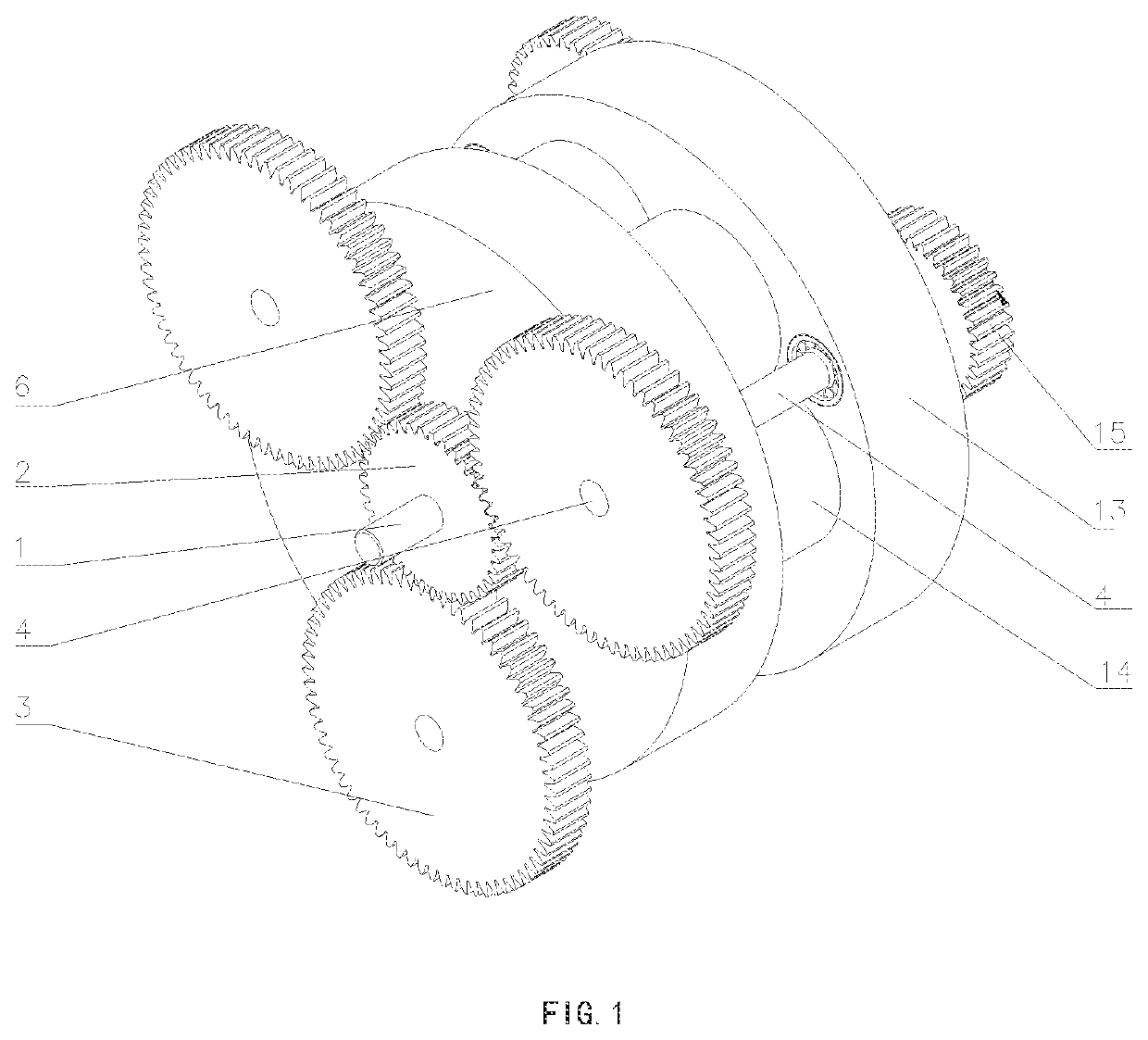
[0039]FIG. 1 to FIG. 5 show a continuously variable transmission of an embodiment of the present invention, which is provided with an input end planetary gear set 101 and an output end planetary gear set 102. A cavity planetary gear carrier 104 is disposed between the input end planetary gear set 101 and the output end planetary gear set 102. The cavity planetary gear carrier 104 includes a cavity input end cover 6 and a cavity output end cover 13. A bucket wheel cavity housing 14 is fixedly disposed between the cavity input end cover 6 and the cavity output end cover 13. An inward side of the input end planetary gear set 101 is connected to the cavity input end cover 6. An inward side of the output end planetary gear set 102 is connected to the cavity output end cover 13. One side of inside of the bucket wheel cavity housing 14 is provided with a bucket wheel planetary gear set 103. The input end planetary gear set 101 includes one input end sun gear 2 and three input end planetary...

embodiment 2

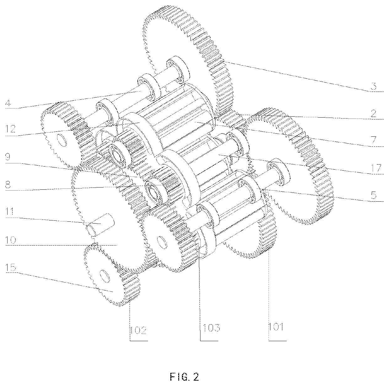
[0046]FIG. 6 to FIG. 9 show a continuously variable transmission of Embodiment 2 of the present invention, which is provided with an input end planetary gear set 101 and a bucket wheel planetary gear set 103. A cavity planetary gear carrier 104 is disposed on an inward side of the input end planetary gear set 101. The cavity planetary gear carrier 104 includes a cavity input end cover 6 and a cavity output end cover 13. A bucket wheel cavity housing 14 is fixedly disposed between the cavity input end cover 6 and the cavity output end cover 13. An output end planetary gear set 102 is disposed between the cavity output end cover 13 and the bucket wheel cavity housing 14. The input end planetary gear set 101 includes one input end sun gear 2 and three input end planetary gears 3. An input shaft 1 is disposed in middle of the input end sun gear 2. The input end sun gear 2 is engaged with the input end planetary gears 3. Planetary gear connecting shafts 4 are disposed in middle of the in...


PUM


Abstract

A continuously variable transmission is provided, solving the technical problems in which a balancing force between a torque-changing bucket wheel and a fluid of a hydraulic two-speed synchronizer is limited, discharging all of the fluid to increase torque results in the loss of flexible transmission, and the structures of control and braking apparatuses are complex. The continuously variable transmission comprises an input end planetary gear set (101) and an output end planetary gear set (102). A cavity planetary gear carrier (104) is disposed between the input end planetary gear set (101) and the output end planetary gear set (102). The cavity planetary gear carrier (104) comprises a cavity input end cover (6) and a cavity output end cover (13). A bucket wheel cavity housing (14) is fixedly disposed between the cavity input end cover (6) and the cavity output end cover (13). An inner side of the input end planetary gear set (101) is connected to the cavity input end cover (6). An inner side of the output end planetary gear set (102) is connected to the cavity output end cover (13). One side inside the bucket wheel cavity housing (14) is provided with a bucket wheel planetary gear set (103). The continuously variable transmission of the invention is widely applicable in the field of transmissions.

Description

BACKGROUND OF THE INVENTIONRelated Applications[0001]This application is a United States National Stage Application filed under 35 U.S.C 371 of PCT Patent Application Serial No. PCT / CN2017 / 116593, filed Dec. 15, 2017, which claims Chinese Patent Application Serial No. CN 201710055648.2, filed Jan. 25, 2017, the disclosure of all of which are hereby incorporated by reference in their entirety.Field of the Invention[0002]The present invention relates to a mechanical transmission device and more particularly, to a flexibly activated continuously variable transmission.Description of the Related Art[0003]In the field of transmission, transmissions are applied most widely in the automobile field. At present, automotive transmissions are classified according to manipulation manner into: manual transmission (MT), automatic transmission (AT) and manual automatic integrated transmission. With the rapid development of automobiles from day to day, the automatic transmission has gradually occupi...

Claims


Application Information

Patent Timeline
Patent Type & Authority Patents(United States)
IPC IPC(8): F16H47/12F16H47/08
CPCF16H47/08F16H47/12F16H2702/00F16H2702/02
Inventor TANG, YONGFENGTANG, YUNING
Owner WEIHAI TUANZHONG TRANSMISSION CO LTD
Why Eureka
Try Eureka