
Curved bezel and curved display apparatus using the same

a display apparatus and curved technology, applied in non-linear optics, instruments, optics, etc., can solve the problems of unstable curvature accuracy, excessive parts, deformation and distortion of edge images, etc., to reduce the weight of the entire machine, reduce the weight of the bezel, and alleviate the effect of unstable curvature of the curved bezel member

Active Publication Date: 2020-06-09
CHONGQING HKC OPTOELECTRONICS TECH CO LTD +1
View PDF14 Cites 0 Cited by
  • Summary
  • Abstract
  • Description
  • Claims
  • Application Information

AI Technical Summary

Benefits of technology

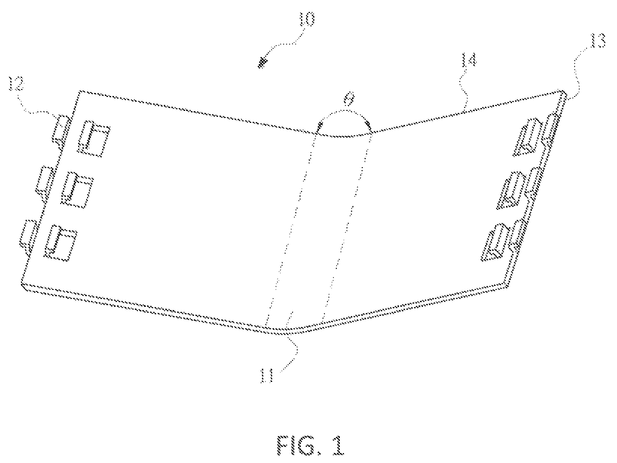
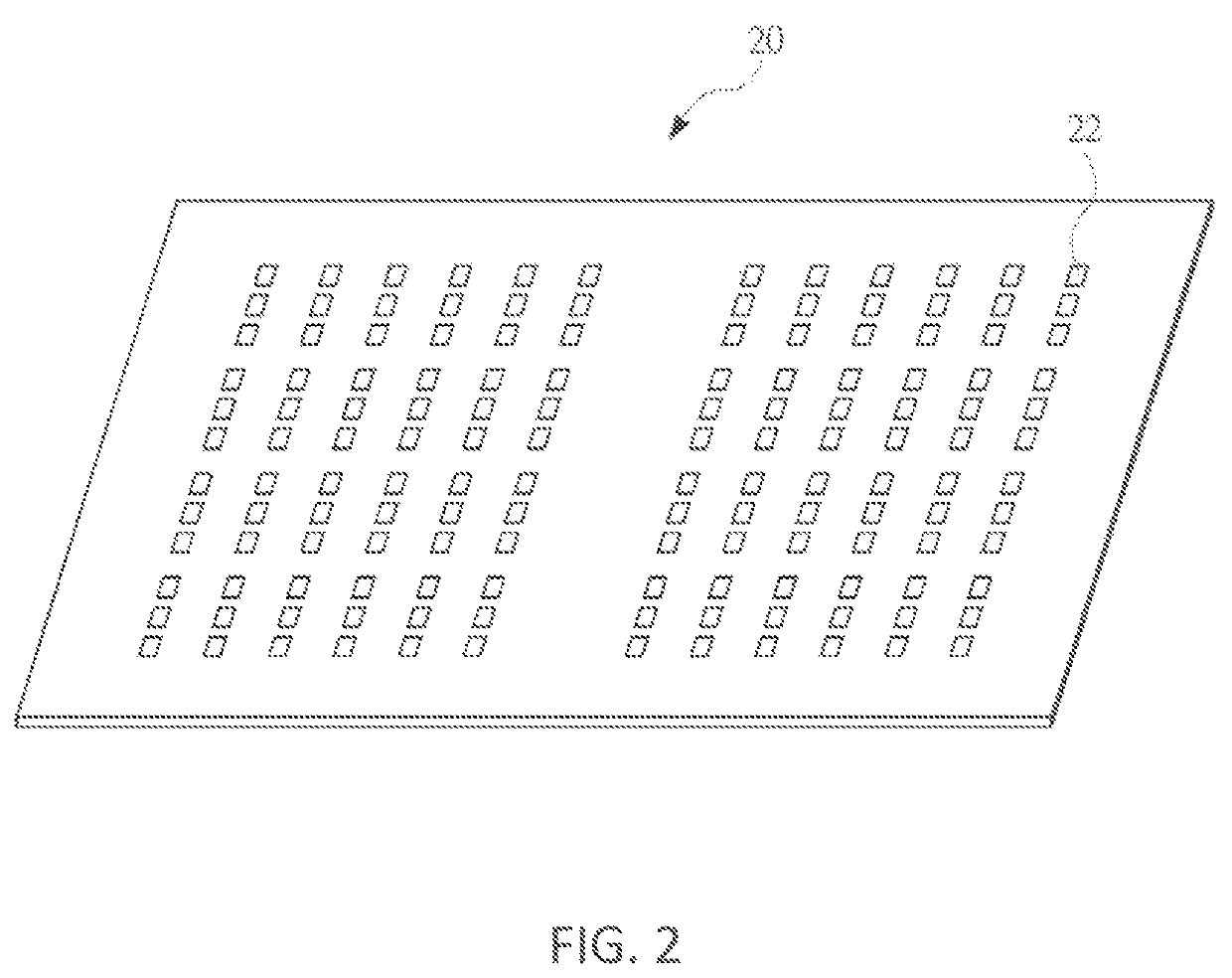
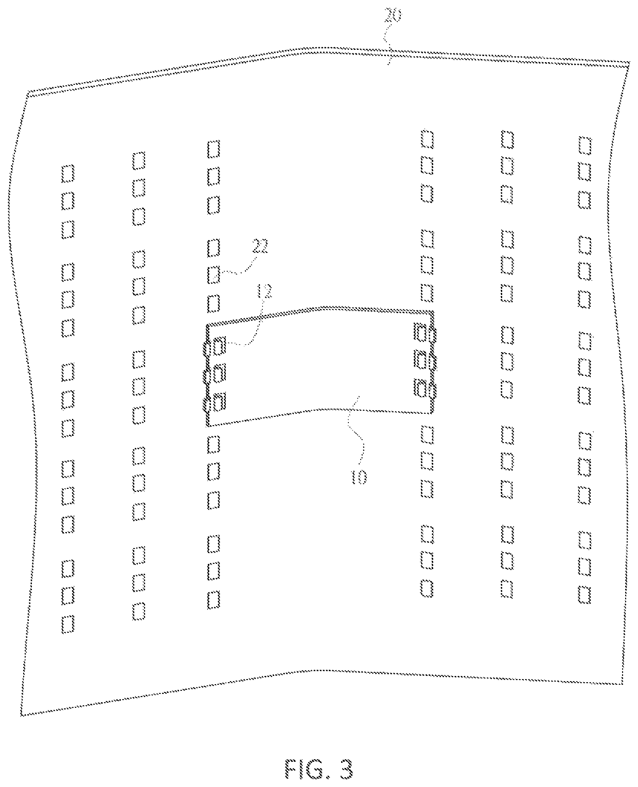
The technical effect of this patent application is to provide a curved bezel that has a stable curvature and reduced weight, which reduces the overall weight of the machine. The bezel can also have variable curvatures achieved by fixing plate members with different curvatures. The bezel is designed to effectively reduce stress and achieve a stable curvature. Additionally, the bezel includes through-holes that are snapped and combined with fixing members, further strengthening the connection.

Problems solved by technology

When a user is watching a television, the distance between an image at the edge of a television screen and eyes of the user becomes larger, resulting in deformation and distortion of the edge image.
However, this method has such problems as unstable curvature accuracy, excessive parts, and difficulty in processing.
However, this method is disadvantageous in that, the integrally formed metal backplane has an unduly large weight and requires high material costs, and after the integrally formed curved bezel is formed, the curvature of the formed backplane is likely to be unstable due to poor stress release of the metal material of the backplane.

Method used


Image

  • Curved bezel and curved display apparatus using the same
  • Curved bezel and curved display apparatus using the same
  • Curved bezel and curved display apparatus using the same

Examples


Embodiment Construction

[0021]The following embodiments are described with reference to the accompanying drawings to give examples of specific embodiments that may be implemented in this application. The terms such as ‘upper’, ‘lower’, ‘front’, ‘behind’, ‘left’, ‘right’, ‘internal’, ‘external’, and ‘side’ provided in this application are merely directions with reference to the accompanying drawings. Therefore, the directional terms are used to illustrate and understand this application rather than to limit this application.

[0022]The accompanying drawings and the descriptions are substantially considered to be exemplary but not to be limiting. In the drawings, a unit having a similar structure is represented by a same reference numeral. In addition, for understanding and ease of description, the size and the thickness of each component shown in the accompanying drawings are arbitrarily shown, but this application is not limited thereto.

[0023]In the accompanying drawings, the thicknesses of layers, films, pa...


PUM

PropertyMeasurementUnit
bending angleaaaaaaaaaa

Abstract

This application relates to a curved bezel and a curved display apparatus using the same. The curved bezel includes: at least one fixing plate member, being a plate and bent of at least one bending angle to form at least one bending, the fixing plate member includes a plurality of fixing members positioned at a periphery of the plate; and a bezel, including a plurality of fasteners corresponding to the fixing members configured to fix with the fasteners, so that the bezel has a curvature same as a curvature of the fixing plate member.

Description

BACKGROUNDTechnical Field[0001]This application relates to a bezel, and in particular, to a curved bezel and a curved display apparatus using the same.Related Art[0002]In recent years, with the improvement of the flat panel display technologies, manufacturers successively launch large-size liquid crystal display panels. When a user is watching a television, the distance between an image at the edge of a television screen and eyes of the user becomes larger, resulting in deformation and distortion of the edge image. Compared with a flat panel, a better viewing effect can be achieved by using a designed curved display apparatus.[0003]In the existing curved surface technologies, the backplane structure of a backlight module is usually implemented by using one of the following two methods. The first method is to form a curved structure by bonding a plurality of segments of bent metal plates. However, this method has such problems as unstable curvature accuracy, excessive parts, and diff...

Claims


Application Information

Patent Timeline
Patent Type & Authority Patents(United States)
IPC IPC(8): G02F1/1333G02F1/13357
CPCG02F1/133308G02F1/1336G02F2001/133314G02F1/1333G02F1/133302G02F1/133608G02F1/133314
Inventor LO, HSU-KANG
Owner CHONGQING HKC OPTOELECTRONICS TECH CO LTD
Learn More