Bidirectional duplex electrical connector

a bidirectional and duplex technology, applied in the field of electrical connectors, can solve the problems of high manufacturing cost of bidirectional electrical connectors, low reliability of functions, and troublesome users, and achieve the effects of reducing manufacturing costs, simplifying stamping, and facilitating assembly

Active Publication Date: 2020-06-09
TOP YANG TECH ENTERPRISE CO LTD
View PDF19 Cites 2 Cited by
  • Summary
  • Abstract
  • Description
  • Claims
  • Application Information

AI Technical Summary

Benefits of technology

[0006]A main object of the invention is to provide a bidirectional duplex electrical connector, wherein the manufacturing and assembling costs can be decreased, and the duplex docking function can be provided.
[0008]Because the rear sections and the fixing portions of the elastically movable portions of the two rows of terminals have the same level and rest against the bottom surfaces of the terminal slots, easy assembling can be achieved and stamping can be simplified, and the manufacturing cost can be decreased. In addition, the rear section of the elastically movable portion of the terminal horizontally rests against the bottom surface of the terminal slot, the support effect of the middle section of the elastic arm can be obtained, thereby increasing the normal force of contacting the terminal and the resilience.

Problems solved by technology

However, most users do not have the habit of placing the electrical plug to face the electrical receptacle in the correct direction, and this mistake-proof function causes docking failure between the electrical plug and the electrical receptacle.
In other words, this mistake-proof function brings troubles to the user on the contrary.
However, the conventional bidirectional electrical connector has the high manufacturing cost, and the low reliability of the function.

Method used


Image

  • Bidirectional duplex electrical connector
  • Bidirectional duplex electrical connector
  • Bidirectional duplex electrical connector

Examples


first embodiment

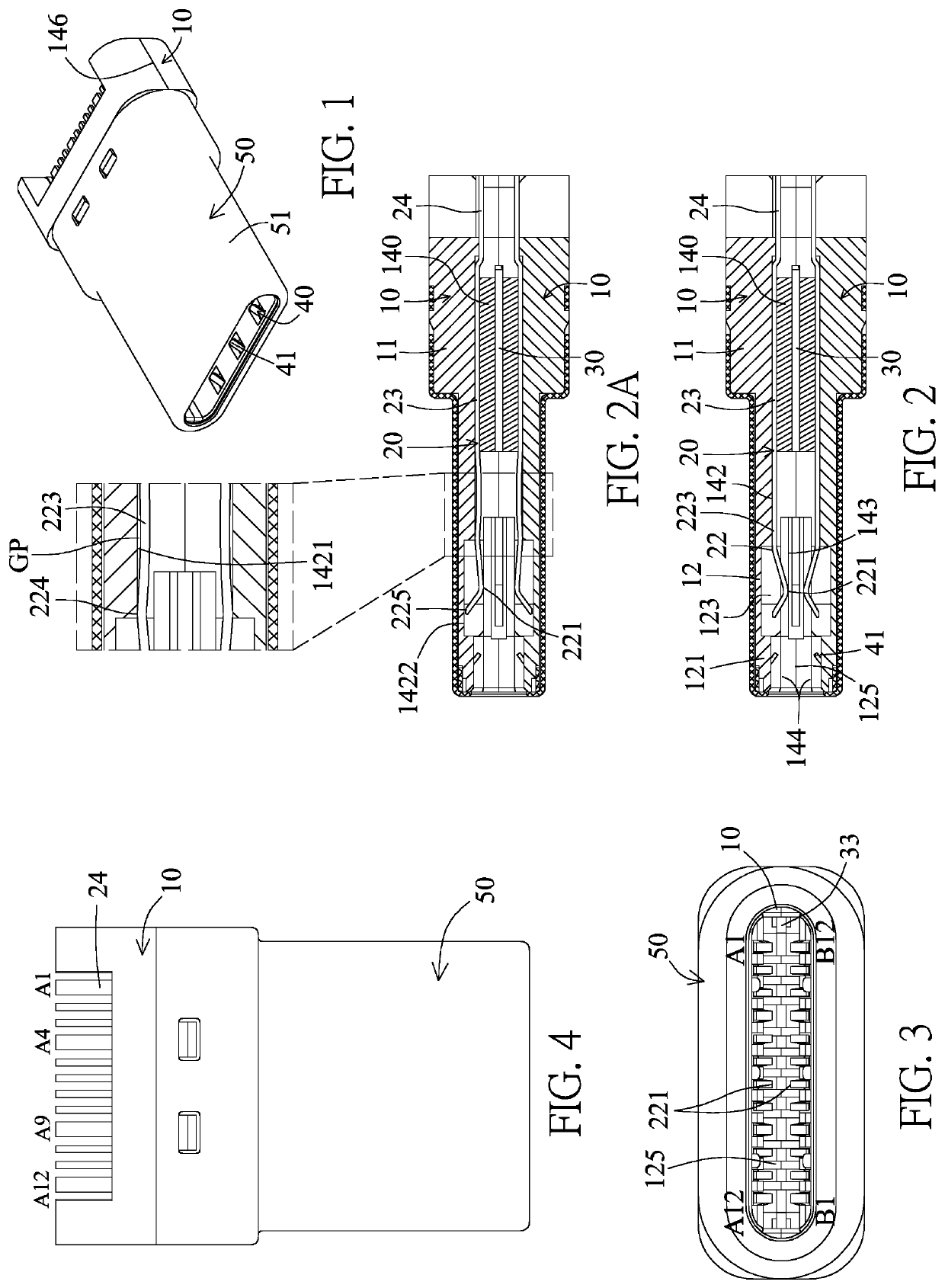
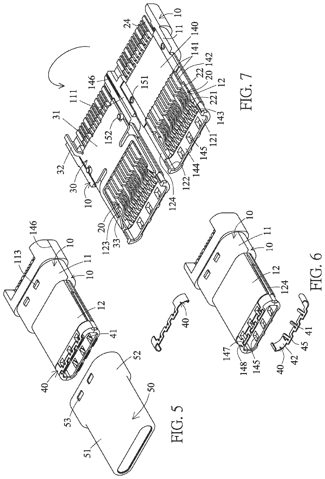
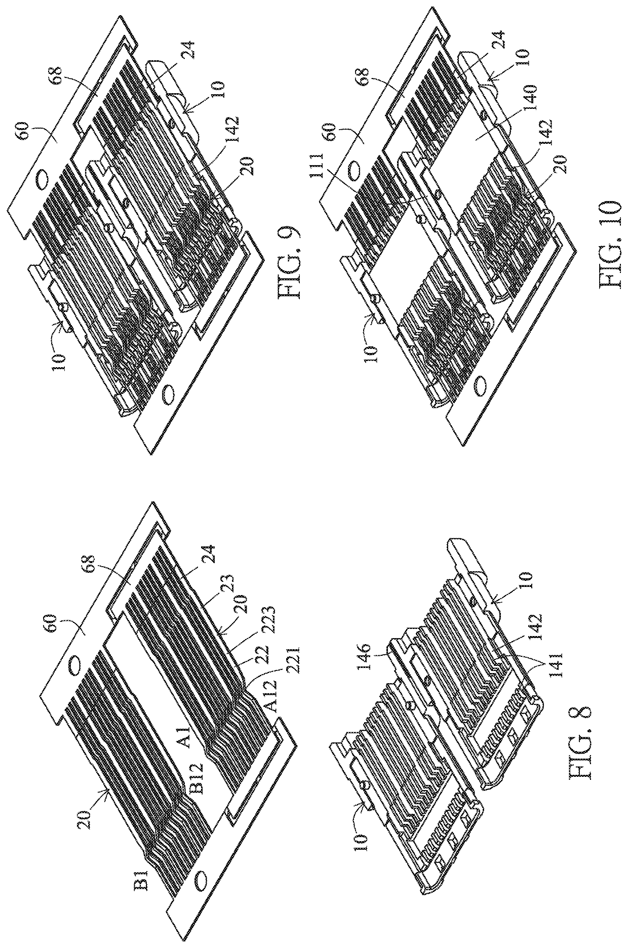
[0071]Referring to FIGS. 1 to 7 a bidirectional duplex USB TYPE-C 3.0 electrical plug according to the invention includes two insulation seats 10, two rows of terminals 20, a metal partition plate 30, two ground members 40 and a metal housing 50.

[0072]The insulation seat 10 is integrally provided with a base portion 11 and a docking portion 12. The docking portion 12 is connected to the front end of the base portion 11. The inner surfaces of the base portions 11 of the two insulation seats are provided with connection surfaces 111 resting against each other. One of the insulation seats is provided with an engagement hole 151 engaging with an engagement column 152 of the other insulation seat. The rear section of the base portion 11 is higher than the front section thereof and the outer surface of the rear section is provided with an engagement block 113. The docking portion 12 is provided with a baseplate 121 and two side plates 122. The two side plates 122 are connected to left and...

sixth embodiment

[0124]Referring to FIGS. 59 and 60, this invention provides a bidirectional duplex USB TYPE-C 3.0 electrical receptacle, which is provided with an insulation seat 10, two rows of terminals 20, a metal partition plate 30, a ground member 40, two insulation layers 90 and a metal housing 50.

[0125]The insulation seat 10 is provided with a base portion 11 and a docking portion, and the docking portion is in the form of a tongue 12.

[0126]The two insulation layers 70 are stacked over the top and bottom surfaces of the metal partition plate 30, and then the two rows of terminals 20 are stacked over the two insulation layers 70. The vertically stacked two rows of terminals, two insulation layers 70 and one metal partition plate 30 are integrally embedded into and fixed to the insulation seat 10 by way of injection molding, and extend from the base portion 11 to the tongue 12.

[0127]Each of the rows of terminals 20 have 12 terminals Each terminal 20 is integrally provided with a front end port...


PUM


Abstract

A bidirectional duplex electrical connector includes: two insulation seats; two rows of terminals assembled into the two rows of terminal slots of the two insulation seats in a vertical direction, wherein the terminal is integrally provided with, from front to rear, an elastically movable portion, a fixing portion and a pin, a front section of the elastically movable portion is curved and provided with a projecting contact, the elastically movable portion is vertically elastically movable, a rear section of the elastically movable portion and the fixing portion are on the same level and rest against a bottom surface of the terminal slot, a depth of the terminal slot is greater than a material thickness of the terminal, and the insulation seat is provided with a fixing structure fixing the fixing portions of the one row of terminals; and a metal housing covering the two insulation seats.

Description

CROSS-REFERENCE TO RELATED APPLICATIONS[0001]This application is a national stage application of PCT Patent Application No. PCT / CN2017 / 072259, filed on Jan. 23, 2017, which claims priority to U.S. Provisional Application No. 62 / 281,756, filed on Jan. 22, 2016, the content of which is incorporated herein by reference. This application is also a continuation-in-part of and claims the benefit of priority from co-pending U.S. patent application Ser. No. 16 / 166,433, filed Oct. 22, 2018, which is a Divisional Application of and claims the benefit of priority from U.S. patent application Ser. No. 15 / 321,373, filed Dec. 22, 2016, now U.S. Pat. No. 10,109,966, the full disclosures of which are incorporated herein by reference.BACKGROUND OF THE INVENTIONField of the Invention[0002]The invention relates to an electrical connector, and more particularly to a bidirectional duplex electrical connector.Description of the Related Art[0003]At present, because the functions of various electronic prod...

Claims


Application Information

Patent Timeline
Patent Type & Authority Patents(United States)
IPC IPC(8): H01R13/64H01R13/642H01R13/6585H01R13/11H01R13/405H01R24/60H01R43/20H01R13/6586H01R43/16H01R107/00
CPCH01R13/6585H01R13/642H01R13/112H01R13/405H01R24/60H01R2107/00H01R43/16H01R13/6586H01R43/20H01R13/506
Inventor TSAI, CHOU HSIEN
Owner TOP YANG TECH ENTERPRISE CO LTD
Why Eureka
Try Eureka