Unlock instant, AI-driven research and patent intelligence for your innovation.

Image encoding device, image decoding device, and program thereof

a technology of image encoding and decoding device, applied in the field of image encoding device, image decoding device, and program thereof, can solve problems such as deteriorating encoding efficiency, and achieve the effects of improving encoding efficiency, high encoding efficiency, and reducing residual component of prediction residual signal

Active Publication Date: 2020-06-09
NIPPON HOSO KYOKAI
View PDF10 Cites 1 Cited by
  • Summary
  • Abstract
  • Description
  • Claims
  • Application Information

AI Technical Summary

Benefits of technology

[0016]An object of the present disclosure is to provide an image encoding device with improved encoding efficiency, an image decoding device, and a program thereof.
[0028]According to the present disclosure, since a signal error occurring between a prediction signal of a predicted image and a neighboring decoded block signal is reduced and encoding efficiency is improved, it is possible to achieve an image encoding device and an image decoding device using a video encoding method with high encoding efficiency. That is, on an encoding side, a residual component in a prediction residual signal can be decreased, and the encoding efficiency can be improved by reducing an amount of information to be encoded and transmitted. Also, on a decoding side, it is possible to perform decoding even with such a reduced amount of information.

Problems solved by technology

However, since this is statistically shown, there is a problem that the encoding efficiency is deteriorated instead by applying a DST in an image out of the statistics (for example, in a case where there is a feature such as strong edges in the vicinity of the periphery of a block of a predicted image).

Method used


Image

  • Image encoding device, image decoding device, and program thereof
  • Image encoding device, image decoding device, and program thereof
  • Image encoding device, image decoding device, and program thereof

Examples


first embodiment

(Image Encoding Device)

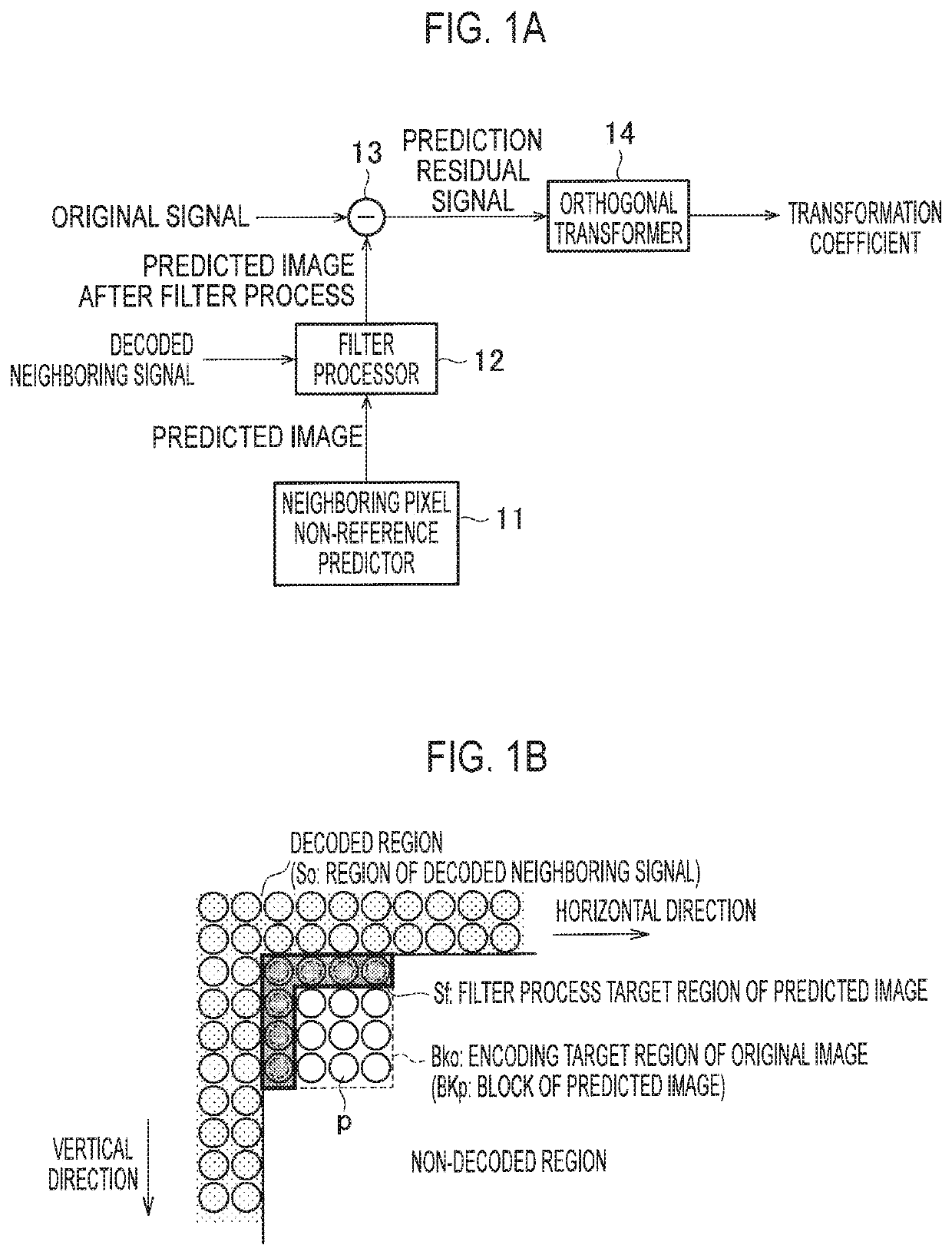
[0059]First, a filter processor 12 related to a predicted image, which is a main component of the present disclosure in an image encoding device 1 according to a first embodiment of the present disclosure, will be described with reference to FIGS. 1 and 2, and a specific typical example of the image encoding device 1 will be described with reference to FIGS. 3 to 5.

[0060]FIG. 1A is a block diagram of a periphery of the filter processor 12 related to the predicted image in the image encoding device 1 according to the first embodiment of the present disclosure, and FIG. 1B is an explanatory diagram illustrating an example of a filter process of the predicted image by the filter processor 12.

[0061]As illustrated in FIG. 1A, the image encoding device 1 according to the first embodiment of the present disclosure includes a neighboring pixel non-reference predictor 11, the filter processor 12, a prediction residual signal generator 13, and an orthogonal transformer ...

second embodiment

[0115]Next, the filter processors 12 and 54 in the image encoding device 1 and the image decoding device 5 according to the second embodiment of the present disclosure will be described with reference to FIG. 8. In the filter processors 12 and 54 of the first embodiment, an example that generates the predicted image including the new prediction signal by performing the low-pass filter process on the prediction signal by using the decoded signals (decoded neighboring signals) neighboring to the left side and the upper side of the predicted image, among the pixel signals (prediction signals) in the block of the predicted image generated by the neighboring pixel non-reference prediction has been described.

[0116]On the other hand, the filter processors 12 and 54 of the present embodiment are configured to perform a correlation determination for determining whether a low-pass filter process is performed on the prediction signal to be subjected to the low-pass filter process by using the ...

third embodiment

(Image Encoding Device)

[0128]Next, the filter processor 12 and an orthogonal transformation selection controller 25 related to a predicted image, which are main components of the present disclosure in the image encoding device 1 according to a third embodiment of the present disclosure, will be described with reference to FIGS. 1B and 11, and image encoding devices 1 of two specific examples will be described with reference to FIGS. 5 and 12 to 15. The following description focuses on differences from the above-described embodiment. That is, in the present embodiment, the same reference numerals are assigned to the same components as those in the above embodiment, and a further detailed description thereof will be omitted.

[0129]FIG. 11A is a block diagram of the periphery of the filter processor 12 and an orthogonal transformation selection controller 25 with respect to a predicted image in the image encoding device 1 according to the present embodiment, and FIG. 1B is an explanator...


PUM


Abstract

An image encoding device is disclosed that performs an operation of generating a predicted image of a target block. The prediction operation is a type of operation that does not use neighboring pixels. The image encoding device further performs operations of performing a low-pass filter process on a prediction signal located at a boundary of the predicted image of the target block, using a decoded neighboring signal, generating a prediction residual signal of target block using the predicted image of the target block, and dividing the prediction residual signal of the target block unit block shapes designated in advance.

Description

RELATED APPLICATIONS[0001]This application is a continuation of PCT / JP2016 / 074293 filed on Aug. 19, 2016, which claims priority to Japanese Application Nos. 2015-163259, 2015-163257 and 2015-163260, all filed on Aug. 20, 2015. The entire contents of these applications are incorporated herein by reference.BACKGROUND OF THE INVENTION1. Field of the Invention[0002]The present disclosure relates to an image encoding device, an image decoding device, and a program thereof, which are applicable to a video encoding method such as MPEG-2, AVC / H.264, MPEG-H, HEVC / H.265, or the like.2. Description of the Related Art[0003]Generally, it is known that an image signal has a high signal correlation between neighboring pixels, regardless of a still image and a moving image. By using this property, for example, two prediction modes of an intra-prediction and an inter-prediction are prepared in a video encoding method such as MPEG-2, AVC / H.264, MPEG-H, or HEVC / H.265. The intra-prediction is a techniq...

Claims


Application Information

Patent Timeline
Patent Type & Authority Patents(United States)
IPC IPC(8): H04B1/66H04N19/61H04N19/117H04N19/46H04N19/593H04N19/625H04N19/12H04N19/147H04N19/176H04N19/105
CPCH04N19/46H04N19/105H04N19/619H04N19/593H04N19/147H04N19/12H04N19/625H04N19/117H04N19/176H04N19/70H04N19/80H04N19/82H04N19/122H04N19/503H04N19/124H04N19/45
Inventor IWAMURA, SHUNSUKEICHIGAYA, ATSUROSAKAIDA, SHINICHI
Owner NIPPON HOSO KYOKAI
Features
  • R&D
  • Intellectual Property
  • Life Sciences
  • Materials
  • Tech Scout
  • Unparalleled Data Quality
  • Higher Quality Content
  • 60% Fewer Hallucinations
Learn More