Milk foaming device and a milk foaming method

a foaming device and milk technology, applied in beverage vessels, cooking vessels, domestic applications, etc., to achieve the effect of improving the quality of milk foam

Active Publication Date: 2020-06-16
EUGSTER FRISMAG
View PDF11 Cites 7 Cited by
  • Summary
  • Abstract
  • Description
  • Claims
  • Application Information

AI Technical Summary

Benefits of technology

[0004]Proceeding from the abovementioned prior art, the invention is based on the object of specifying a comfortable manageable milk frothing apparatus, by way of which filling of milk froth into a drinking vessel is possible without tipping of the entire container. The milk frothing apparatus is preferably to be distinguished by an improved milk froth quality.
[0011]In order to optimize the milk froth quality, it is advantageously provided in one development of the invention that the feed rotor is assigned at least one air line for sucking in air, in particular by way of the rotation of the feed rotor, preferably exclusively by way of the said rotation. As will still be explained later, the air line preferably opens into a frothing chamber which encloses the feed rotor at least in sections or into a fluid connection between the frothing chamber and the supply space which is delimited by the container and has a greater volume than the frothing chamber. With regard to the arrangement of the air line, there are different possibilities. It is thus conceivable, for example, to route the air line upwards, starting from a surrounding region of the feed rotor, in particular in a region of a container edge or above the latter, at any rate preferably in a region above a maximum or permissible milk filling level in the supply space which is delimited by the container, in order thus to ensure an entry of air (and preferably no entry of milk). In addition or as an alternative, an air line can also be routed downwards to a container underside and / or can be arranged there. It is also conceivable in addition or as an alternative to route an air line outwards in the radial direction, in particular to arrange it in a circumferential wall of the container or to penetrate the circumferential wall. For the case of the lateral or radial opening of the air line outwards or the opening of the air line downwards out of the container, said air line can be assigned an automatically switching check valve in one development of the invention, which check valve opens during rotation of the feed rotor in order to suck in air and closes the air line in the case of a decreasing rotational speed or a feed rotor which is switched off, in order to prevent an exit of milk outwards out of the air line.
[0012]It has proven particularly expedient if the feed rotor is arranged at least in sections, preferably completely, in a frothing chamber which is connected to the supply space in a fluid-conducting manner, in particular is arranged in the container at a spacing from a container upper side, and out of which the milk froth line opens. By way of the arrangement of the feed rotor in a frothing chamber which is delimited structurally with respect to the supply space, the milk froth quality can be increased and the conveying property of the feed rotor can be improved; the latter, in particular, on account of the additional utilization of the volumetric increase of the milk froth compared with the milk to convey the milk froth through the feed line. In other words, by way of the provision of a frothing chamber which receives the feed rotor at least in sections, preferably completely, the froth or its volumetric increase can be channelled in an improved manner and therefore contributes, in addition to the rotational movement of the feed rotor, to the conveying of the milk froth in the direction of the drinking vessel via the milk froth line which is preferably configured as a riser. It is preferred here if the milk froth line opens from an otherwise preferably closed upper side of the frothing chamber.
[0014]With regard to the specific realisation of the frothing chamber, it is advantageous if the frothing chamber is delimited by a housing which is arranged in the container and, in particular, in a lower container region and separates the frothing chamber volume from the supply space volume, the housing interior space, that is to say the frothing chamber and the supply space being connected to one another via the abovementioned fluid-conducting connection.

Problems solved by technology

It is a disadvantage in the case of the known container that the container has to be tipped over for emptying into a cup, by the entire container being handled or tipped.

Method used


Image

  • Milk foaming device and a milk foaming method

Examples


Embodiment Construction

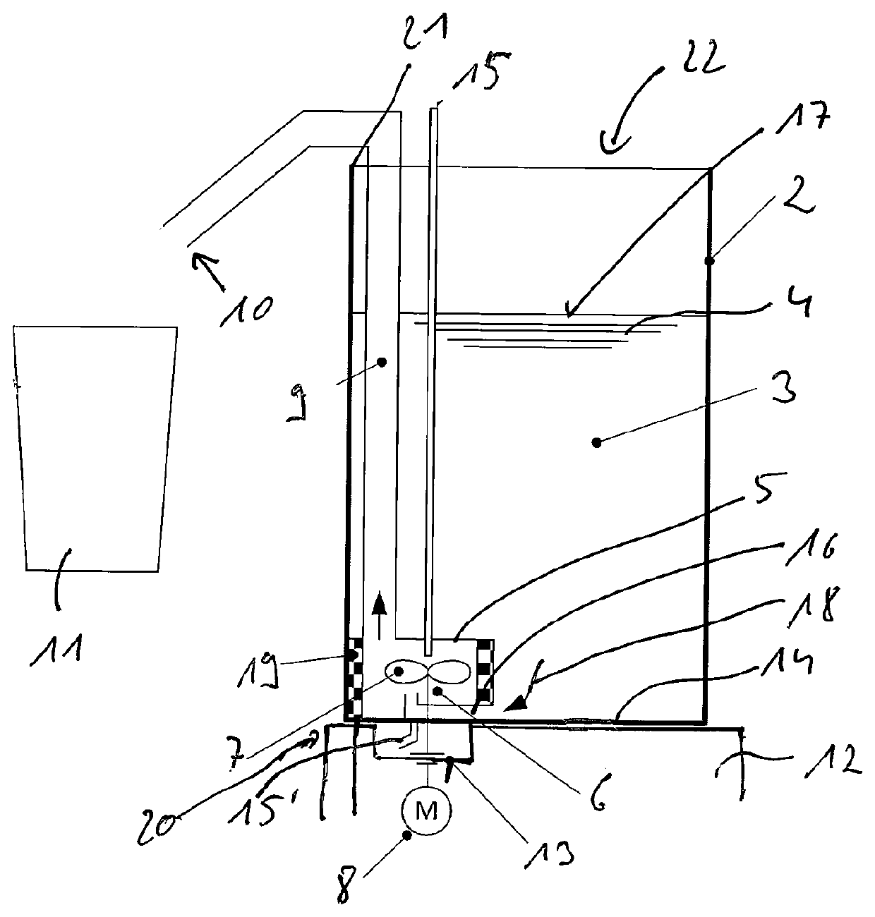
[0027]FIG. 1 shows a milk frothing apparatus 1. The said milk frothing apparatus 1 comprises a container 2 which, in its interior, delimits a supply space 3 for milk 4 to be frothed, into which supply space 3 milk can be filled manually through an upper, open filling opening 22.

[0028]A frothing element which is configured as a feed rotor 7, as an impeller wheel in the specific exemplary embodiment, and can be driven by means of an electric motor 8 is arranged in a lower region of the container 2 within a frothing chamber 6 which is delimited by a housing 5. By way of the rotation of the feed rotor 7 about its rotational axis, milk is frothed within the frothing chamber 6, and is conveyed towards an outlet 10 through a milk froth line 9 which is configured as a riser, opens out of the frothing chamber 6 and rises upwards in the vertical direction, and the said milk passes through the said outlet 10 into a drinking vessel 11 which is positioned below the outlet 10.

[0029]It can be seen...


PUM


Abstract

Milk frothing apparatus (1) having a container (2) which delimits a supply space (3) for milk (4), and having a frothing element which can be rotated by electric motor with the function of frothing the milk (4) by way of rotation of the frothing element, the supply space being assigned a filling opening (22), wherein the frothing element is configured as a feed rotor (7), with the function of conveying, by way of the rotation of said feed rotor (7), the milk which was frothed by way of rotation of the frothing element (7) to an outlet (10) through a milk froth line (9) of the milk frothing apparatus (1), and wherein the feed rotor (7) is arranged at least in sections, preferably completely, in a frothing chamber (6) which is connected in a fluid-conducting manner to the supply space (3), from which frothing chamber (6) the milk froth line (9) opens, and wherein the feed rotor (7) is assigned at least one airline (15, 15′) for sucking in air by way of the rotation of the feed rotor (7), and wherein the air line (15, 15′) opens into the frothing chamber (16) or the fluid-conducting connection (16) between the supply space (3) and the frothing chamber (6).

Description

BACKGROUND OF THE INVENTION[0001]The invention relates to a milk frothing apparatus, having a container which delimits a supply space for milk, and having a frothing element which can be rotated by electric motor for frothing the milk, the supply space being assigned a (preferably upper) filling opening for filling milk (preferably manually). Furthermore, the invention relates to a frothing method for frothing milk, in particular by way of a milk frothing apparatus according to the invention.[0002]EP 1 827 188 B1 has disclosed a milk frothing apparatus which has a container which is open at the top and delimits a supply space for milk, a frothing element which is configured as a whisk being arranged directly in the supply space, by way of which frothing element the milk can be frothed. Via a magnetic coupling, the frothing element is driven via an electric motor which is arranged in a station which is separate from the container. It is a disadvantage in the case of the known contain...

Claims


Application Information

Patent Timeline
Patent Type & Authority Patents(United States)
IPC IPC(8): A47J31/44A47J27/00A47J43/07A47J43/046
CPCA47J31/4489A47J31/4485A47J27/004A47J43/0465A47J43/0716
Inventor FISCHER, DANIEL
Owner EUGSTER FRISMAG
Why Eureka
Try Eureka