
Intelligent door lock system for use with a door assembly

a door lock and intelligent technology, applied in mechanical control, instruments, gearing, etc., can solve the problems of affecting the overall aesthetic appeal of the room, requiring current electronic lock manufacturers to create additional, and unwanted inconvenien

Active Publication Date: 2020-06-16
OTTO LLC +1
View PDF24 Cites 12 Cited by
  • Summary
  • Abstract
  • Description
  • Claims
  • Application Information

AI Technical Summary

Benefits of technology

The present invention provides a door lock system that is easy to mount and use, aesthetically pleasing, and provides sufficient operational functionality and access control. The system includes an inner bezel assembly, an outer bezel assembly, and a deadbolt assembly. The deadbolt assembly can be coupled to the outer bezel assembly either directly or through an extension component. The extension component and / or the deadbolt assembly can be coupled to the outer bezel assembly via a twist-lock feature. The latch assembly interacts with a torque link assembly to move between the deployed and retracted positions. The torque link assembly includes a torque link, ejector spring, ejector element, latch cam, and ejection ramp. The latch assembly includes a latch element, springs, and retaining plates. The torque link moves the latch element from the normally biased deployed position to the retracted position. The ejector element moves through and outwardly from an opening to press or push against a portion of the housing of the puck assembly. The movement of the latch element into the retracted position enables the puck assembly to be removed from the inner bezel assembly.

Problems solved by technology

Either an unauthorized access or an unintended refusal of access can have financial consequences and / or cause delay and disruption in service or result in unwanted inconvenience.
A disadvantage of this prior art configuration is that it compels current electronic lock manufacturers to create additional “real-estate” in the lock assembly to accommodate the additional structure that is necessary to operate the electronic door lock.
Consequently, the prior art devices are quite large and hence conspicuous when mounted on the door assembly, thus affecting the overall aesthetic appeal of the room, while concomitantly providing limited operational functionality.
As a result of the disparate control systems and separate methods for granting permissions, it is often inconvenient for a user or administrator to access, program and control each security device or system efficiently.
Furthermore, self-contained, on-site security systems or devices can be compromised or malfunction without being able to issue notification to an interested party.

Method used


Image

  • Intelligent door lock system for use with a door assembly
  • Intelligent door lock system for use with a door assembly
  • Intelligent door lock system for use with a door assembly

Examples


Embodiment Construction

[0096]The intelligent door lock system of the present invention is sized and configured so as to maintain all feature sets or components in a generally centrally located, compact fashion that does not impede on the surrounding door surfaces. Further, the door lock system of the present invention is easy to install and set-up, and hence easy to use.

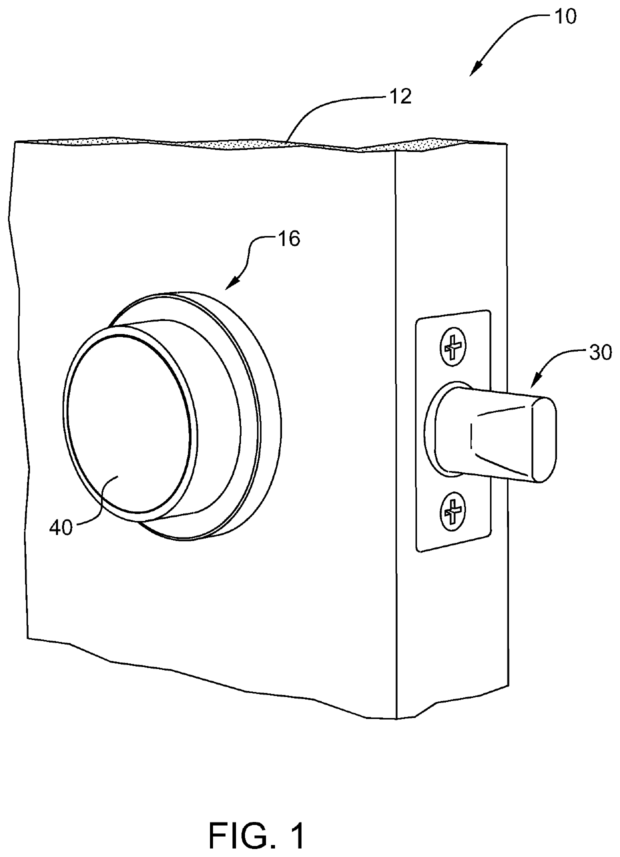
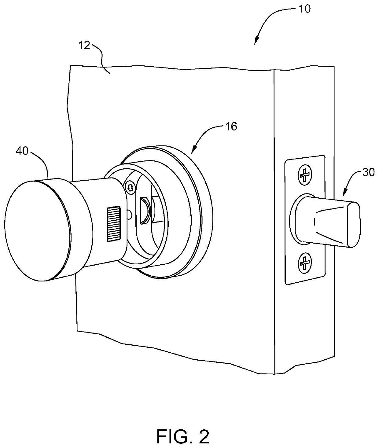
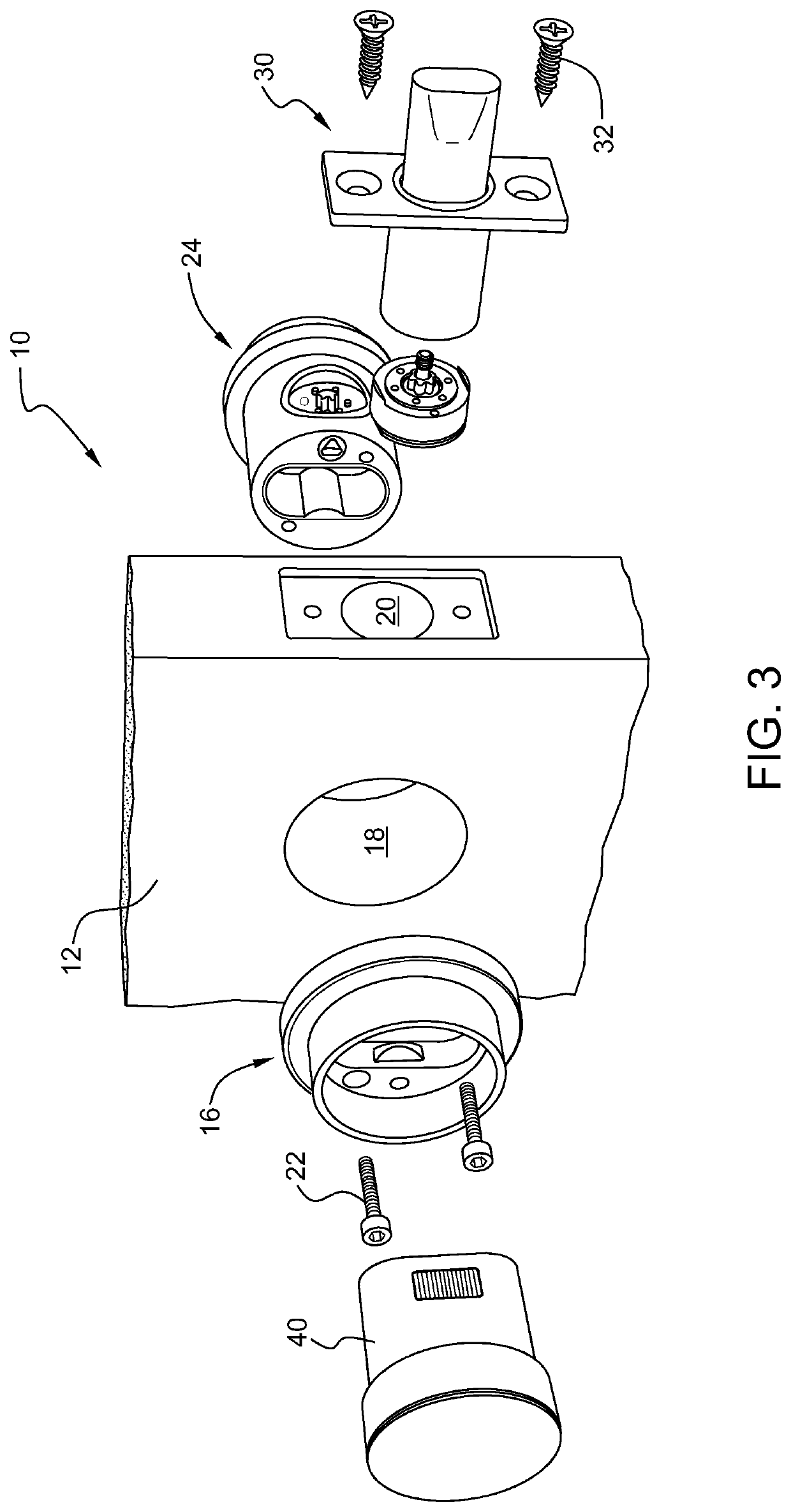
[0097]The intelligent door lock system 10 of the present invention is illustrated for example in FIGS. 1-4C. The door lock system 10 is shown mounted within a door panel 12 of a door assembly. The door assembly can also include a frame element (not shown) for mounting a strike cup assembly 1002. The door lock system 10 according to the present invention includes an inner bezel assembly 16 and an outer bezel assembly 24 that is mounted within a bore 18 formed in the door panel 12. A deadbolt assembly 30 is mounted within a transverse bore 20 formed within a side of the door panel and which communicates with the central bore 18 as is known i...


PUM


Abstract

An intelligent door lock system that permits both electronic and manual control of a deadbolt. The door lock system can include an inner bezel assembly, an outer bezel assembly, and a deadbolt assembly, where the deadbolt assembly can be coupled to the outer bezel assembly via a twist-lock feature. The inner bezel assembly also includes a puck assembly that seats within an inner bezel. The puck assembly can be retained within or released from the inner bezel via a latch assembly. The outer bezel assembly includes a display assembly that seats within an outer bezel. The outer bezel is coupled to a motor chassis assembly that includes a motor and gear assembly having a series of gears that translate movement of dial elements or a motor into movement of a bolt element between locked and unlocked positions.

Description

RELATED APPLICATION[0001]The present application is related to U.S. provisional patent application Ser. No. 62 / 256,637, entitled Intelligent Door Lock System For Use With A Door Assembly, filed on Nov. 17, 2015, the contents of which are herein incorporated by reference.FIELD OF THE INVENTION[0002]The present invention relates generally to intelligent door lock systems, and more particularly relates to an intelligent, electronic dead bolt assembly for use with a door assembly.BACKGROUND OF THE INVENTION[0003]As is known in the art, mechanically and electro-mechanically operated door assemblies serve an important function at both commercial and residential sites, ensuring that personnel and / or visitors who are not authorized to access the particular premises are restricted from such access, while concomitantly providing access to authorized parties. Either an unauthorized access or an unintended refusal of access can have financial consequences and / or cause delay and disruption in se...

Claims


Application Information

Patent Timeline
IPC IPC(8): E05B9/02E05B45/00E05B41/00E05B53/00E05B47/00F16H19/00E05B17/00E05B17/10G08B5/36G07C9/00
CPCE05B17/0075E05B45/00E05B9/02F16H19/001E05B53/008E05B47/0012E05B41/00E05B17/0083E05B17/10G08B5/36G07C9/00309E05B2047/0048E05B2047/0097G07C2009/00769E05B17/226E05B47/026E05B2047/002E05B2047/0058E05B2047/0065G07C9/00174G07C9/00666G07C2209/62
Inventor FUNAMURA, JOSHUALYLYK, NICOLAS PEDROKESSLER, PATRICKJADALLAH, ERICFOUNTAIN, JORDANMURPHY, ROBERT SEANSATTERFIELD, PHILLIPSPRINGER, GREGMORGENSTERN, DAVID
Owner OTTO LLC
Learn More