Powered surgical drill with integral depth gauge that includes a probe that slides over the drill bit

a drill bit and probe technology, applied in the field of powered surgical drills, can solve the problems of screw not securely holding the nail, screw can extend an excessive distance out beyond the bone, screw exposed end can rub against the surrounding tissue,

Active Publication Date: 2020-06-30
STRYKER CORP
View PDF145 Cites 354 Cited by
  • Summary
  • Abstract
  • Description
  • Claims
  • Application Information

AI Technical Summary

Benefits of technology

[0010]This invention is related to a new and useful drill capable of simultaneously drilling a bore in tissue and providing a measure of bore depth. The drill of this invention is designed so that the depth measuring components do not appreciably obstruct the field of view of the tissue against which the drill bit is applied. A further feature of this invention is that presence of the depth measuring components do not require the surgeon to appreciable enlarge the size of the incision adjacent the bone in order to accommodate the depth measuring components.
[0012]To facilitate the close position of the probe relative to the drill bit, the drill bit extends forward from a cannulated rotor that provides the rotational moment that rotates the drill bit. Within the bore of the rotor, there is void space dimensioned to receive the proximal portion of the probe. In this version of the invention, the drill bit is mounted to a coupling assembly attached to the proximal end of the rotor. In some versions of the invention, the rotor is the rotor internal to the motor. In other versions of invention, this rotor is separate from the motor. A gear assembly connects the rotating shaft of the motor to this rotor so that the rotation of the motor shaft results in the rotation of the rotor that turns the drill bit and that receives the proximal end of the probe.

Problems solved by technology

If the screw is too short, the screw may not securely hold the nail into which the screw is inserted in place.
If the screw is too long, the screw can extend an excessive distance out beyond the bone.
If the screw extends an excessive distance beyond the bone, the exposed end of the screw can rub against the surrounding tissue.
If this event occurs, the tissue can against which the screw rubs can be damaged.
A disadvantage of this protocol is that after the bore is formed, the surgeon must take the time to: insert the depth gauge in the bore; position the gauge properly to ensure the bore depth is accurately measured; read the gauge to determine bore depth; and withdraw the gauge.
Having to perform these sub-steps adds to the overall time it takes to perform a surgical procedure.
A problem with this type of drill is that the rod, which is spaced away from the drill bit by a distance of 0.5 cm or more, and the head, which can have a diameter of 0.8 cm or more, obstruct the surgeon's view of the tissue against which the drill bit is pressed.
For this reason, this particular type of drill has not proven to be a popular device for forming a bore while simultaneously providing a measure of bore depth.

Method used


Image

  • Powered surgical drill with integral depth gauge that includes a probe that slides over the drill bit
  • Powered surgical drill with integral depth gauge that includes a probe that slides over the drill bit
  • Powered surgical drill with integral depth gauge that includes a probe that slides over the drill bit

Examples


Embodiment Construction

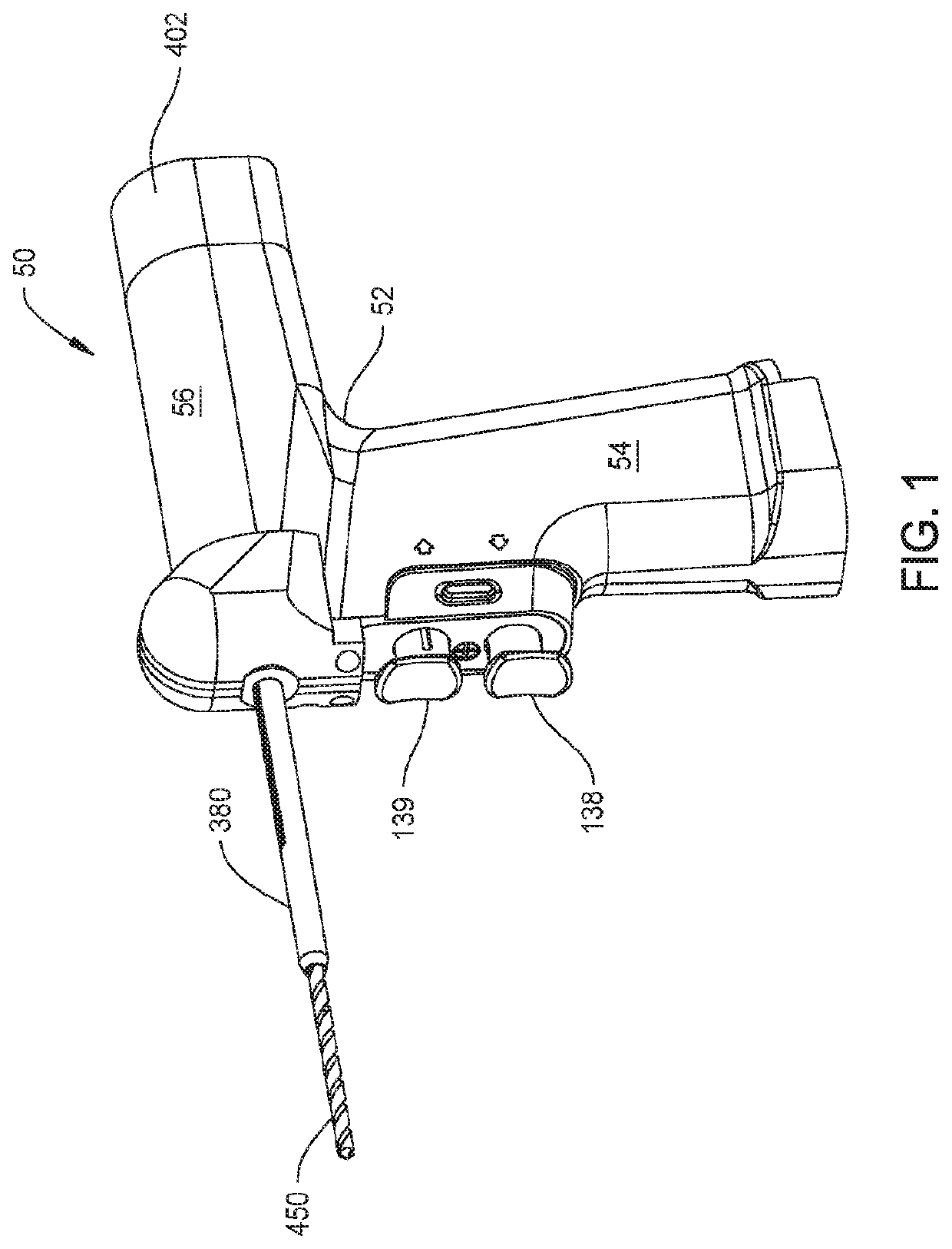
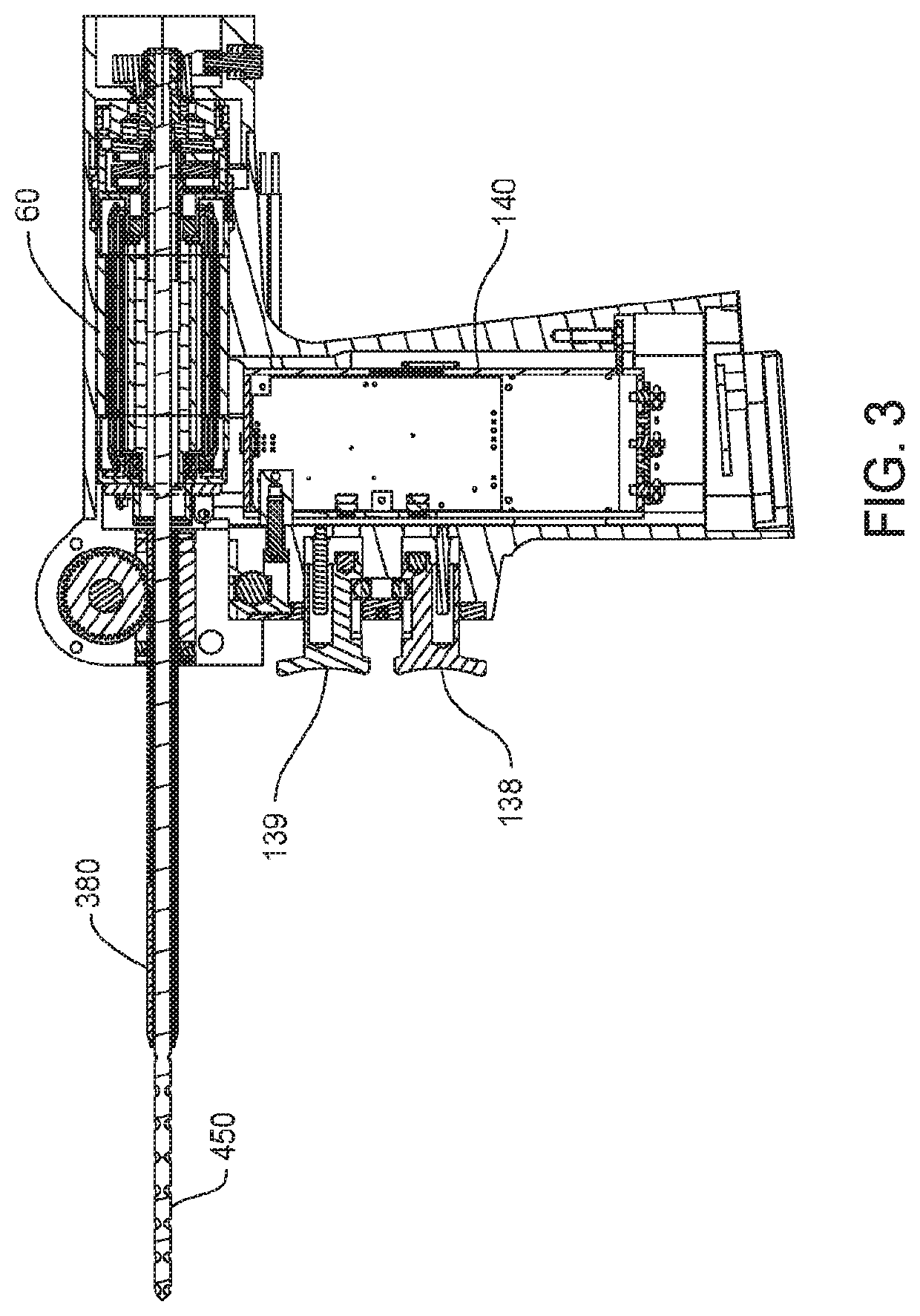
[0052]FIGS. 1-3 illustrate a surgical drill 50 of this invention and a drill bit 450 that extends from and is rotated by the drill 50. Drill 50 includes a housing 52. In the illustrated version of the invention, drill housing 52 is pistol shaped. The housing 52 has a grip 54. A barrel 56, also part of the housing 52, is located above and extends proximally away from the grip 54. (“Proximally” is understood to mean towards the practitioner holding the drill 50; away from the site to which the drill bit 450 is applied. “Distally” is understood to mean away from the practitioner holding the drill 50; towards the site to which the drill bit 450 is applied.) A motor 60 is disposed in the handpiece barrel 56. The drill bit 450 is connected to the motor 60 to be rotated by the motor. A display 410 is mounted to the proximal end of the barrel 56.

[0053]Power for energizing the motor 60 is typically provided by a battery (not illustrated) attached to the butt end of the handgrip 54. One such ...


PUM


Abstract

A drill for driving a drill bit into a solid object such as bone. The drill includes a rotor with a bore that transmits rotational movement to the drill bit. The drill bit extends through the rotor bore. A probe extends forward from the drill to measure bore depth. The probe is moveably mounted to the drill so as to extend into the rotor bore. As the drill and drill bit advance forward the probe remains static. As a result of the advancement of the drill the rotor extends over the proximal end of the probe.

Description

CROSS-REFERENCE TO RELATED APPLICATIONS[0001]This application is the National Stage of International Patent Application No. PCT / US2016 / 049899, filed on Sep. 1, 2016, which claims priority to and all the advantages of U.S. Provisional Patent Application No. 62 / 213,916, filed on Sep. 3, 2015, the content of each of which is incorporated herein by reference.FIELD OF THE INVENTION[0002]This invention relates generally to a powered surgical drill. The powered surgical drill of this invention includes a depth gauge that measures bore depth and that does not appreciably interfere with the view of the tissue into which the associated drill bit is driven.BACKGROUND OF THE INVENTION[0003]One type of powered surgical tool used in orthopedic surgery is the surgical drill. This type of tool includes a housing that contains a motor. A coupling assembly, also part of the drill, releasably holds a drill bit to the motor so that, upon actuation of the motor, the drill bit rotates. As implied by its ...

Claims


Application Information

Patent Timeline
Patent Type & Authority Patents(United States)
IPC IPC(8): A61B17/16A61B90/00
CPCA61B17/1615A61B90/03A61B17/1622A61B90/06A61B17/1628A61B17/1633A61B17/1626A61B2090/062A61B17/1624A61B2090/036
Inventor CARUSILLO, STEVE
Owner STRYKER CORP
Why Eureka
Try Eureka