Warm air channel outlet control device

a control device and warm air channel technology, applied in vehicle heating/cooling devices, vehicle cleaning, vehicle components, etc., can solve the problems of affecting the discharge of warm air from the warm air duct, which flows substantially perpendicular to the axis of rotation, and could be blocked, in the worst cas

Active Publication Date: 2020-06-30
HANON SYST
View PDF52 Cites 0 Cited by
  • Summary
  • Abstract
  • Description
  • Claims
  • Application Information

AI Technical Summary

Benefits of technology

[0017]According to the design of the present invention, the mode control damper of an air outlet and the warm air duct discharge opening are thus designed and disposed in such a way that the mode control damper is able to control the volume of air exiting the warm air duct to the corresponding outlet. The advantage of the invention is that it therefore enables the temperature of an outlet to which air from the warm air duct can be supplied to be controlled dependent on the mode. The invention involves an optimization of a warm air duct combined with a mode control damper whereby the temperature layering function of a heating and air conditioning system can be improved. The features of the invention can be implemented easily and without substantial added cost.
[0018]There are two different preferred embodiments for the solution according to the invention. In both embodiments, segments on the mode door, preferably formed as circular segments, prevent warm air from flowing out parallel to the axis of rotation. As mentioned above, this applies to the entire adjustment range of the mode control damper. The outlet of the warm air duct is configured accordingly.
[0019]According to one advantageous embodiment, the warm air duct discharge opening extends in a direction from the rotational axis of the mode control damper up to an opposing sealing edge against which the mode control damper rests in the closed state. The warm air duct discharge opening of the warm air duct thus preferably extends between the rotational axis of the mode control damper and a housing wall of the housing. The segments of the mode control damper are preferably positioned and aligned in such a way that, as the mode control damper rotates, they pass outside of the warm air duct alongside walls of the warm air duct which are disposed opposite one another and are oriented perpendicular to the axis of rotation.
[0020]According to the second preferred embodiment, the warm air duct discharge opening extends alongside walls of the warm air duct, which are disposed opposite one another and are oriented perpendicular to the axis of rotation, from a first housing side up to a second, opposite housing side of the housing. In this case, the lateral segments are attached and positioned on the mode control damper in such a way that, as the mode control damper rotates about the rotational axis, the segments move in cutouts in the side walls of the warm air duct at the warm air duct discharge opening, each of the cutouts being formed as complementary to the lateral segments. This can be achieved, for example, by designing the lateral segments in the form of circular segments and the complementary cutouts in the side walls of the warm air duct at the warm air duct discharge opening as half-moon shaped, and by the circular segments then moving in the cutouts as the mode control damper rotates.
[0021]The mode control damper and / or the warm air duct may have one or more openings, and / or a small distance may be provided between the warm air duct discharge opening and the mode control damper in the closed state, either of which will result in the warm air duct discharge opening not being completely closed even when the mode control damper is in the closed state. Even when the mode control damper is closed, the design according to the invention will operate with constant ventilation due to the openings or the distance between the warm air duct discharge opening and the mode control damper. It is therefore unnecessary for the warm air duct to be completely closed.
[0022]According to one embodiment of the invention, at least one baffle plate is formed at the warm air duct for conducting a portion of the air flow from the warm air duct so as to bypass the mode control damper.

Problems solved by technology

If cold air were to flow parallel to the axis of rotation and into the region of the warm air duct discharge opening, the discharge of warm air from the warm air duct discharge opening, which flows substantially perpendicular to the axis of rotation, could be impeded and in the worst case even blocked.

Method used


Image

  • Warm air channel outlet control device
  • Warm air channel outlet control device
  • Warm air channel outlet control device

Examples


Embodiment Construction

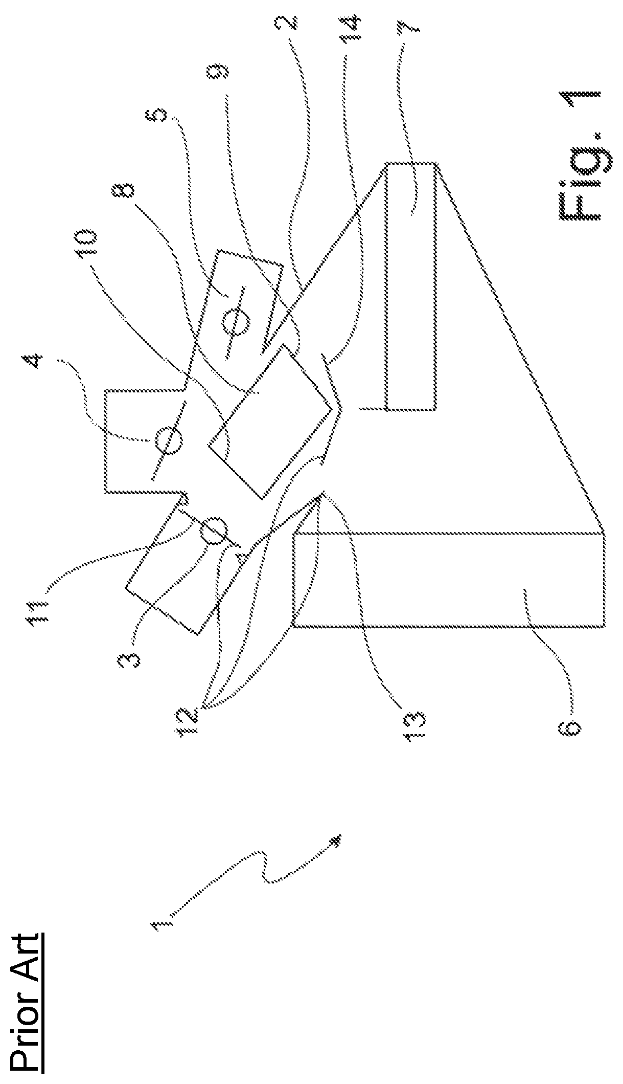
[0035]FIG. 1 shows a heating and air conditioning system 1 according to the prior art. This system comprises a housing 2 having one air inlet and three air outlets 3, 4, 5. In FIG. 1, a defrost outlet 3, a dashboard outlet 4 and a foot well outlet 5 are illustrated schematically. The incoming air is conducted across an evaporator 6, which cools the air. Connected downstream of evaporator 6 in terms of flow is a heating heat exchanger 7, across which a portion of the air that was previously cooled by evaporator 6 flows. Another portion of the cooled air is conducted past heating heat exchanger 7, rather than across it. In other words, a warm air path extends across heating heat exchanger 7 toward air outlets 3, 4, 5 and a cold air path extends directly toward air outlets 3, 4, 5, bypassing the heating heat exchanger.

[0036]Inside housing 2, a separate warm air duct 8 having a warm air duct intake opening 9 and a warm air duct discharge opening 10 is positioned, this separate duct bein...


PUM


Abstract

A heating and air conditioning system for a motor vehicle including a housing having an air outlet, a heating heat exchanger disposed inside the housing with a warm air path to heat air flowing therethrough, a warm air duct having a warm air intake opening and a warm air duct discharge opening disposed downstream of the heating heat exchanger channeling a partial flow of warm air from the warm air path to the air outlet, and a mode control damper rotatable about a rotational axis and connected downstream of the warm air duct in terms of flow, wherein the air outlet may be selectively opened completely or partially, and in a closed state may be partially or completely closed. The mode control damper functions simultaneously as the control damper for controlling the volume of air exiting the warm air duct discharge opening.

Description

CROSS-REFERENCE TO RELATED PATENT APPLICATIONS[0001]This patent application claims the benefit of German Patent Application No. 10 2015 122 348.1 filed Dec. 21, 2015. The disclosure of the above patent application is hereby incorporated herein by reference in its entirety.FIELD OF THE INVENTION[0002]The invention relates to a heating and air conditioning system for a motor vehicle. This system comprises a housing having one or more air outlets, at least one heating heat exchanger and / or one heater, which is / are disposed inside the housing and over which a warm air path extends so that air flowing through the warm air path is heated as it passes across the heating heat exchanger and / or the heater. The heating and air conditioning system further comprises a warm air duct having a warm air intake opening and a warm air duct discharge opening, which is disposed downstream of the heating heat exchanger and / or the heater for the purpose of channeling a partial air flow of warm air from th...

Claims


Application Information

Patent Timeline
Patent Type & Authority Patents(United States)
IPC IPC(8): B60H1/00B60S1/02B60S1/54
CPCB60S1/54B60H1/00678B60S1/023B60H2001/00721B60H1/00071B60H2001/00092B60H1/00835B60H1/00842B60H1/00857
Inventor KLEIN, TORSTENHANDWERK, DETLEFFERREIRA, ANTONIO MARQUESWIESMANN, RALPH
Owner HANON SYST
Why Eureka
Try Eureka