Transmission park control system

a technology of transmission park and control system, which is applied in mechanical equipment, transportation and packaging, and machining, etc., can solve the problems of overriding the selection of drivers, and achieve the effect of increasing the rate of pressure drop and increasing the pressure drop in the line pressure circui

Active Publication Date: 2020-06-30
FORD GLOBAL TECH LLC
View PDF13 Cites 0 Cited by
  • Summary
  • Abstract
  • Description
  • Claims
  • Application Information

AI Technical Summary

Benefits of technology

[0005]A method of engaging a transmission park mechanism includes commanding a reduction in line pressure and commanding engagement of the first shift element for a predetermined duration. Commanding engagement of the first shift element increases a rate of decrease of pressure in a line pressure circuit without resulting in actual clutch engagement. When a fluid temperature is greater than a threshold, commanding engagement of the first shift element is inhibited. The method may also include commanding engagement of a second shift element for a predetermined duration, thereby further increasing the rate of decrease of pressure in the line pressure circuit. The method may further include commanding release of third and fourth shift elements.
[0007]A transmission includes a park valve and a controller. The park valve has a spool mechanically linked to a park mechanism. The spool is biased toward a park position by pressure in a pump out circuit and biased toward an out-of-park position by pressure in an out-of-park circuit. The park valve fluidly connects the out-of-park circuit to a line pressure circuit when the spool is in the out-of-park position. The controller is programmed to respond to a driver command to engage the parking mechanism by commanding a reduction in pressure in the line pressure circuit and by commanding engagement of a first shift element for a predetermined duration, thereby increasing a rate of decrease of pressure the line pressure circuit. The controller may be further programmed to inhibit commanding engagement of the first shift element in response to a fluid temperature being greater than a threshold. The controller may be further programmed to respond to the driver command to engage park by also commanding engagement of a second shift element for the predetermined duration, thereby further increasing the rate of decrease of pressure in the line pressure circuit. The controller may be further programmed to respond to the driver command to engage park by also commanding release of third and fourth shift elements.

Problems solved by technology

However, there are some conditions in which the transmission may over-ride the driver selection.

Method used


Image

  • Transmission park control system
  • Transmission park control system
  • Transmission park control system

Examples


Embodiment Construction

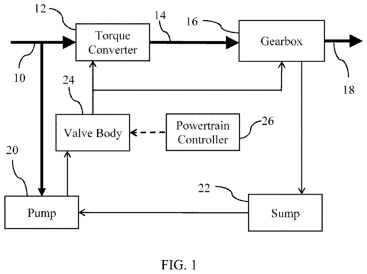
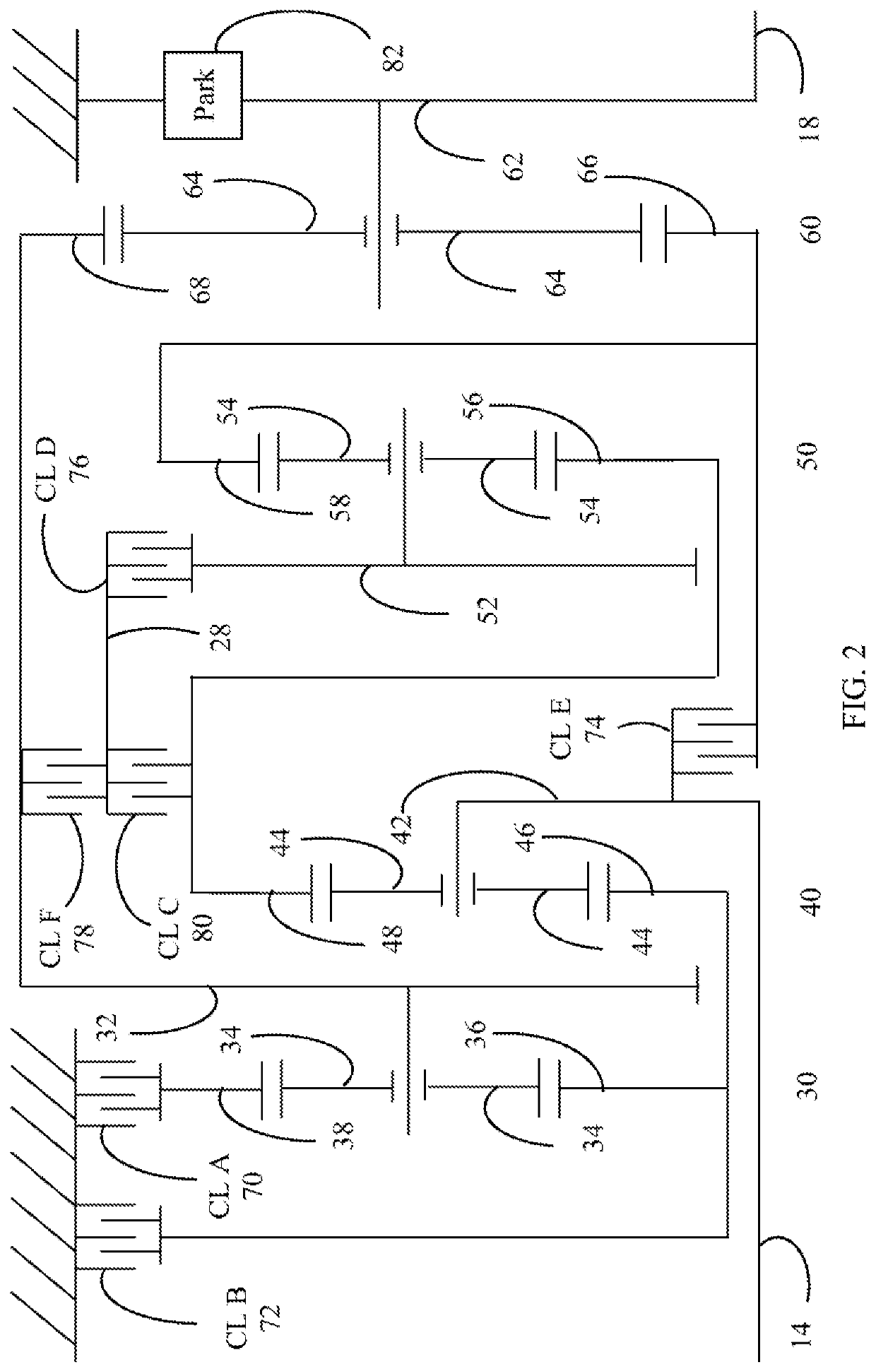
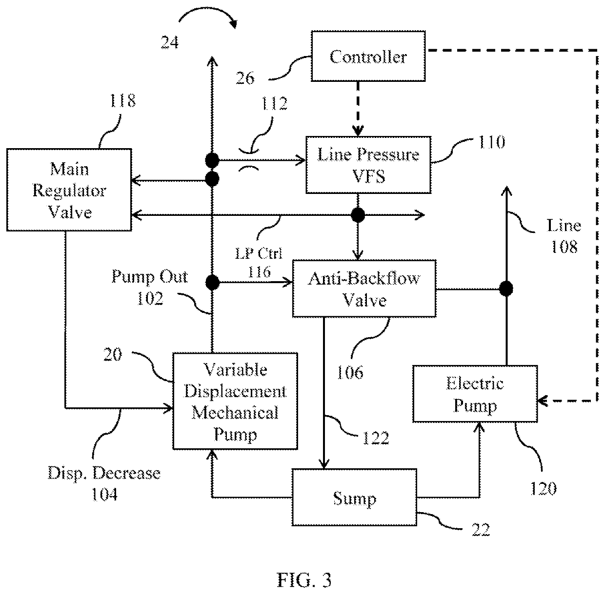
[0016]Embodiments of the present disclosure are described herein. It is to be understood, however, that the disclosed embodiments are merely examples and other embodiments can take various and alternative forms. The figures are not necessarily to scale; some features could be exaggerated or minimized to show details of particular components. Therefore, specific structural and functional details disclosed herein are not to be interpreted as limiting, but merely as a representative basis for teaching one skilled in the art to variously employ the present invention. As those of ordinary skill in the art will understand, various features illustrated and described with reference to any one of the figures can be combined with features illustrated in one or more other figures to produce embodiments that are not explicitly illustrated or described. The combinations of features illustrated provide representative embodiments for typical applications. Various combinations and modifications of ...


PUM


Abstract

A park valve performs a multi-plexing function in which an out-of-park circuit is connected to line pressure when the valve is in an out-of-park position and is vented when the valve is in a park position. When particular clutches are released, the out-of-park circuit biases the park valve toward the out-of-park position. To engage park, a controller commands a low line pressure, reducing the forces that bias the park valve toward the out-of-park position. To accelerate the pressure decay in the line pressure circuit, thereby decreasing the time required to achieve park, the controller commands engagement of one or more shift elements.

Description

TECHNICAL FIELD[0001]This disclosure relates to the field of hydraulic control systems for automatic transmissions for motor vehicles. More particularly, the disclosure relates to a system of engaging and disengaging a parking pawl.BACKGROUND[0002]Many vehicles are used over a wide range of vehicle speeds, including both forward and reverse movement. Some types of engines, however, are capable of operating efficiently only within a narrow range of speeds. Consequently, transmissions capable of efficiently transmitting power at a variety of speed ratios are frequently employed. When the vehicle is at low speed, the transmission is usually operated at a high speed ratio such that it multiplies the engine torque for improved acceleration. At high vehicle speed, operating the transmission at a low speed ratio permits an engine speed associated with quiet, fuel efficient cruising. Typically, a transmission has a housing mounted to the vehicle structure, an input shaft driven by an engine...

Claims


Application Information

Patent Timeline
Patent Type & Authority Patents(United States)
IPC IPC(8): F16H63/34F16H63/48F16K11/07F16H61/00F16H3/66F16H59/72
CPCF16H61/0031F16H63/483F16H63/3483F16K11/0704F16H2200/0069F16H2200/2046F16H59/72F16H2200/2012F16H3/66
Inventor GITTINS, SCOTT JOSEPHFEDULLO, TIMOTHYGLAUBER, SAMUEL MELVILLEKINCH, DEREKSLAYTON, JOSEPH SCOTT
Owner FORD GLOBAL TECH LLC
Why Eureka
Try Eureka