
Trans inductor and power converter using the same

a technology of inductor and power converter, which is applied in the direction of dynamo-electric converter control, process and machine control, instruments, etc., can solve the problems of increasing the efficiency of an inverter that directly influences fuel efficiency, increasing the ripple current that flows in an hdc converter module, and increasing the size or cost. , to achieve the effect of reducing the output rms current, reducing the peak current flowing in an inverter power module, and improving the efficiency

Active Publication Date: 2018-08-21
HYUNDAI MOTOR CO LTD
View PDF10 Cites 1 Cited by
  • Summary
  • Abstract
  • Description
  • Claims
  • Application Information

AI Technical Summary

Benefits of technology

The patent provides a new design for a trans inductor and power converter that can reduce the peak current in an inverter power module, improve efficiency, and reduce output RMS current. By using a material that is strong against current saturation, the inductor can decrease its inductance faster when high current is generated, and prevent a sudden increase in current flow in a switch device. This results in lower capacitor consumption and improved performance of the power converter.

Problems solved by technology

In particular, an increase in efficiency of an inverter that directly influences fuel efficiency has become a significant issue and a high-voltage direct current to direct current (DC-DC) converter (HDC) that boost a battery voltage to enhance a voltage input to an inverter to thereby improve efficiency of the inverter has been researched.
Additionally, the size or costs also increase.
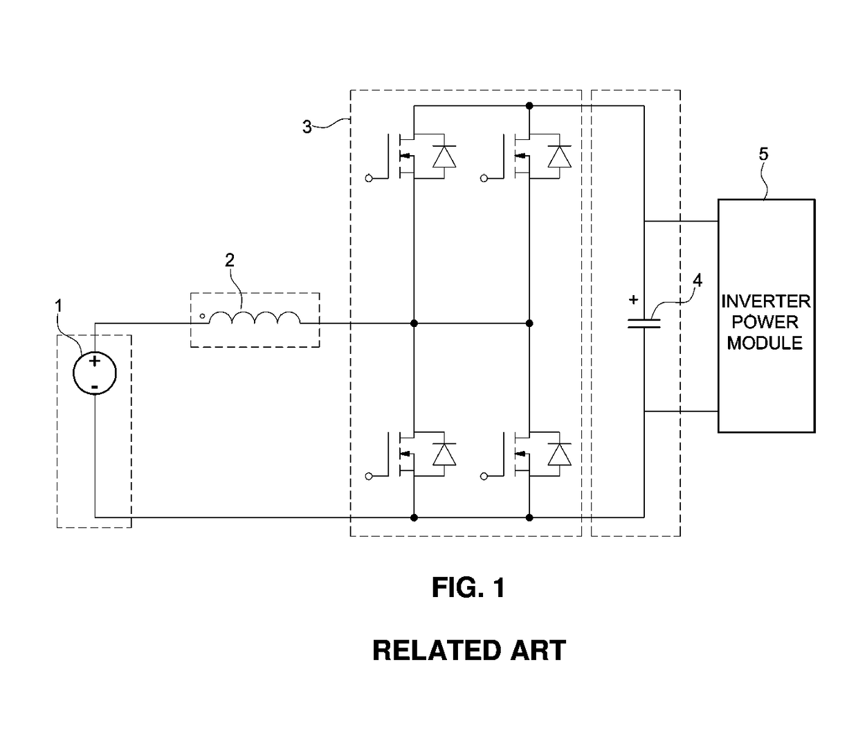
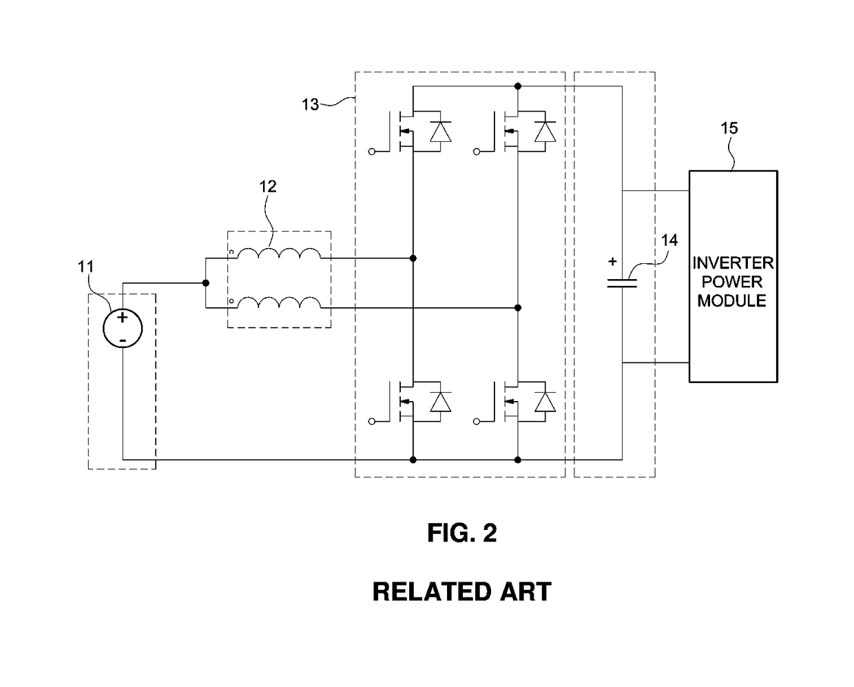
An interleave inductor provides for a reduction in ripple current that flows into a capacitor to be reduced by half, however, ripple current that flows in an HDC converter module increases and the loss also increases.
For example, in a vehicle system that instantaneously generates high current, when a core formed of ferrite is used the core is saturated due to generation of high peak current and unique properties of a magnetic substance may be lost.
Accordingly, capacitance is required to increase and high-peak current generates high noise which reduces electromagnetic waves of vehicles and the lifetime of components.
However, high-peak current flows in the HDC converter module 13 which increases switching loss and noise and the electromagnetic waves of vehicles and lifetime of the components are adversely affected.

Method used


Image

  • Trans inductor and power converter using the same
  • Trans inductor and power converter using the same
  • Trans inductor and power converter using the same

Examples


example 1

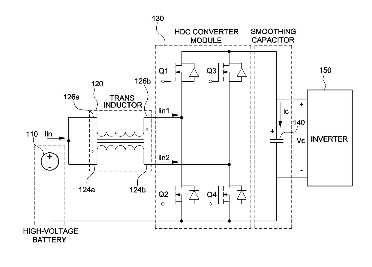
[0043]A transformer-type two-phase inductor (a trans inductor) configured to include two coil portions formed by winding wires at opposite sides of a Hiflux core formed by compressing Hiflux powder. The Hiflux powder is compressed in the form of a rectangular ring and connected between a lithium battery of about 200 V and an HDC converter module. A capacitor is connected to an output port of the HDC converter module to design a circuit formed by omitting an inverter power module from the structure of FIG. 6.

experimental example 1

[0047]In the circuits of Example 1 and Comparative Examples 1 and 2, Root-mean-square (RMS) current of each capacitor and ripple current of each HDC converter module are measured. Accordingly, the measurement results are shown in FIG. 8. Inductor efficiency of each circuit according to output power of each circuit is shown in FIG. 9.

experimental example 2

[0048]In particular, the on / off operations of a switch device in a circuit may be configured to be adjusted under the substantially similar conditions. The voltage and current applied to the trans inductor of Example 1 and voltage and current applied to the trans inductor of Comparative Example 3 are measured to calculate inductance of each inductor, and the calculation result is shown in FIG. 10.

[0049]As seen from FIG. 8, RMS current of a capacitor, measured in the circuit of Example 1, has value less than the RMS current of a capacitor, measured in the circuits of Comparative Examples 1 and 2. Accordingly, the capacitor size and capacitance may be reduced in the circuit of Example 1. Additionally, the ripple current of the HDC converter module, measured in the circuit of Example 1, has a value less than the ripple current of the HDC converter module, measured in the circuits of Comparative Examples 1 and 2. Accordingly, efficiency of a switch device may be increased and heating ma...


PUM

PropertyMeasurementUnit
input voltageaaaaaaaaaa
voltageaaaaaaaaaa
output voltageaaaaaaaaaa

Abstract

A trans inductor having a powdery magnetic substance and a power converter using the trans inductor are provided. The trans inductor and the power converter reduce peak current flowing in an inverter power module (IGBT), improve inverter efficiency, reduce output RMS current (output effective current) and reduce capacitor consumption by applying a material with properties that are resistant against current saturation instead of a core material of a conventional trans inductor employed in a power converter. Accordingly, an inductance decreasing rate due to core saturation when high current is generated is improved and current flowing in a switch device is prevented from being abruptly increased.

Description

CROSS-REFERENCE TO RELATED APPLICATION[0001]This application claims under 35 U.S.C. § 119(a) the benefit of priority to Korean Patent Application No. 10-2016-0108047 filed on Aug. 25, 2016, the entire contents of which are incorporated herein by reference.BACKGROUND[0002](a) Field of Disclosure[0003]The present disclosure relates to a trans inductor and a power converter using the same, and more particularly, to a trans inductor and a power converter that improve system efficiency of eco-friendly vehicles such as a plug-in hybrid vehicle and an electric vehicle.[0004](b) Description of the Related Art[0005]Recently, the emergence of global environmental problems has created an interest in eco-friendly vehicles. In particular, an increase in efficiency of an inverter that directly influences fuel efficiency has become a significant issue and a high-voltage direct current to direct current (DC-DC) converter (HDC) that boost a battery voltage to enhance a voltage input to an inverter t...

Claims


Application Information

Patent Timeline
Patent Type & Authority Patents(United States)
IPC IPC(8): H02P1/00H02M7/44H01F17/04H01F38/42H02P6/08H01F27/255H02M3/158H01F3/10
CPCH01F38/42H01F27/255H02M3/158H02P6/085H02M7/44H02P2201/07H01F3/10H01F30/06H02M1/32H02M3/155H02M3/1584H01F3/14H01F37/00H02M1/0064H01F27/26H01F27/28
Inventor LEE, DAE WOOYANG, SI HUNYANG, JIN YOUNGYEO, IN YONGSONG, BYEONG SEOBLEE, WOO YOUNG
Owner HYUNDAI MOTOR CO LTD
Learn More