Cooling member and power storage module

a technology of power storage module and cooling member, which is applied in the direction of indirect heat exchangers, electrochemical generators, light and heating apparatus, etc., can solve the problems of increasing the pressure within the pipe, increasing manufacturing costs, and using a pipe with relatively high strength, so as to reduce the manufacturing cost of a cooling member or a power storage element, the heat dissipation properties of the power storage element can be improved, and the effect of reducing the manufacturing cos

Active Publication Date: 2020-06-30
AUTONETWORKS TECH LTD +2
View PDF25 Cites 0 Cited by
  • Summary
  • Abstract
  • Description
  • Claims
  • Application Information

AI Technical Summary

Benefits of technology

[0004]According to the above-described configuration, in order to enclose the heat transfer fluid, the pipe is required to have certain strength. The reason for this is that, when the heat transfer fluid receives heat from a heat-generating body and evaporates, the volume of the heat transfer fluid increases, resulting in an increase in the pressure within the pipe. Enclosing the heat transfer fluid in the pipe in a fluid-tight manner and using a pipe having relatively high strength have increased manufacturing costs.
[0005]The present design was made based on circumstances such as those described above, and it is an object thereof to provide a cooling member that can be manufactured at a reduced cost and a power storage module using the cooling member.

Problems solved by technology

The reason for this is that, when the heat transfer fluid receives heat from a heat-generating body and evaporates, the volume of the heat transfer fluid increases, resulting in an increase in the pressure within the pipe.
Enclosing the heat transfer fluid in the pipe in a fluid-tight manner and using a pipe having relatively high strength have increased manufacturing costs.

Method used


Image

  • Cooling member and power storage module
  • Cooling member and power storage module
  • Cooling member and power storage module

Examples


embodiment 1

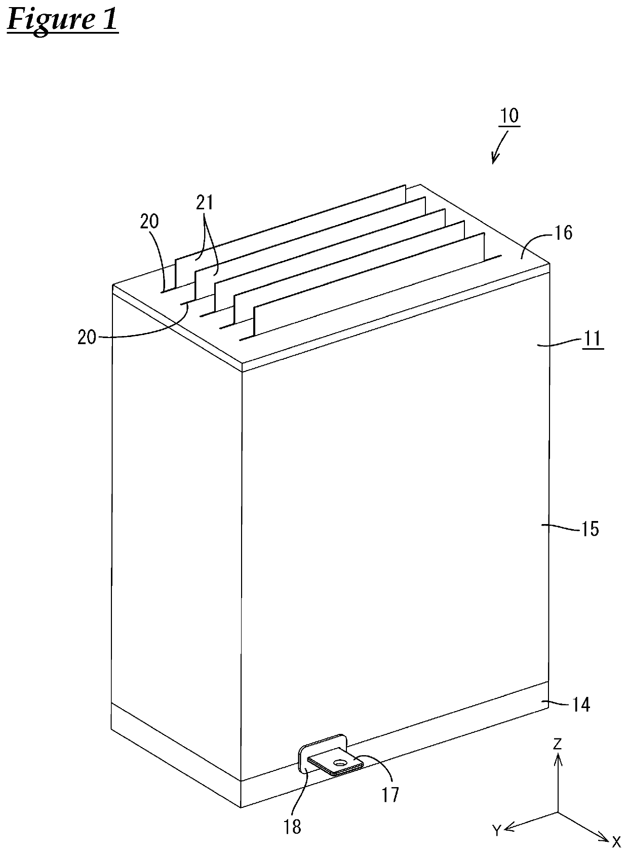
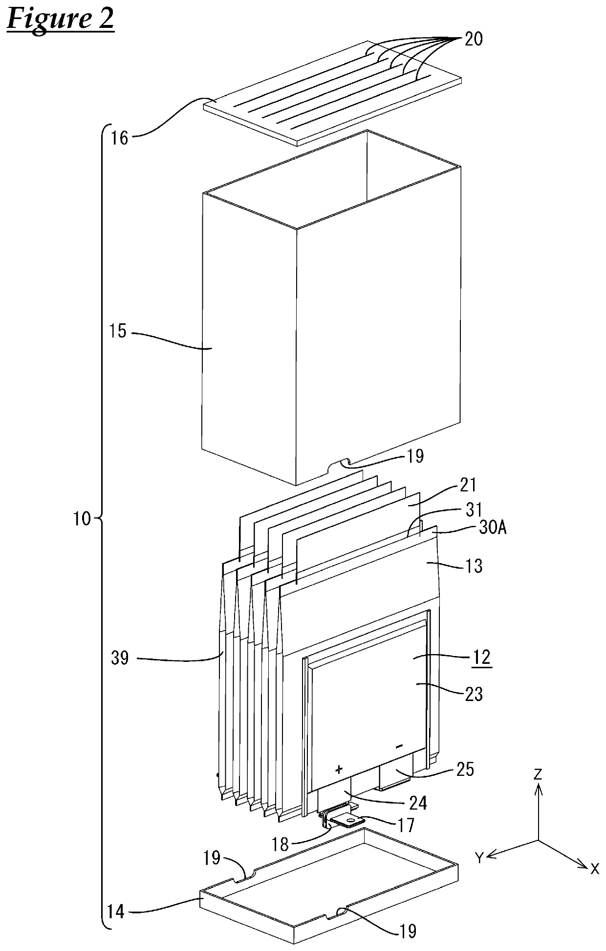
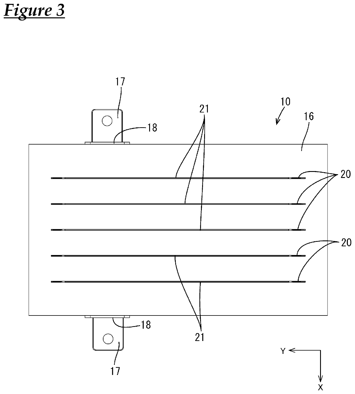
[0047]Embodiment 1 will be described with reference to FIGS. 1 to 14. A power storage module 10 according to the present embodiment includes a housing 11, power storage elements 12 that are accommodated in the housing 11, and cooling members 13 that are accommodated in the housing 11 and that are in contact with a portion of an outer surface of the power storage elements 12. In the following description, a direction X is taken as the right side, a direction Y as the front side, and a direction Z as the upper side. Also, with respect to a plurality of members having the same shape, at least one of those members may be denoted by a reference numeral, and the reference numeral may be omitted from the other members.

[0048]As shown in FIG. 1, the housing 11 has a substantially rectangular parallelepiped shape as a whole. As shown in FIG. 2, the housing 11 includes a lower case 14 that is open upward and that has a substantially rectangular shape when viewed from above, a rectangular tube-...

embodiment 2

[0083]Next, Embodiment 2 will be described with reference to FIGS. 15 to 22. As shown in FIGS. 16 and 17, in a power storage module 70 according to the present embodiment, a plurality of (six in the present embodiment) power storage elements 12 are lined up in a housing 71, with a cooling member 50 being interposed between adjacent power storage elements 12. A plurality of (five in the present embodiment) cooling members 50 are accommodated in the housing 71.

[0084]As shown in FIGS. 18 and 19, in each cooling member 50, at the joint portion 30A that is formed at an upper end edge of a sealed body 51, a heat dissipation plate 53 made of a metal is fluid-tightly joined to an inner surface of a first laminated sheet 54 and an inner surface of a second laminated sheet 55 via a sealing material 56. In the drawings, a configuration is shown in which the sealing material 56 is applied to the heat dissipation plate 53 side; however, a configuration may also be adopted in which the sealing ma...


PUM

PropertyMeasurementUnit
heat absorptionaaaaaaaaaa
internal volumeaaaaaaaaaa
strengthaaaaaaaaaa

Abstract

A cooling member includes a fluid-tight sealed body that is formed by a first laminated sheet and a second laminated sheet being joined to each other at at least one joint portion, a coolant that is enclosed in the sealed body, and a heat dissipation plate that is joined in a fluid-tight manner to an inner surface of the sealed body at at least one joint portion and that has a heat absorption portion that is located inside the sealed body and a heat dissipation portion that is located outside the sealed body.

Description

CROSS REFERENCE TO RELATED APPLICATIONS[0001]This application claims the priority of Japanese patent applications JP2015-055921 filed on Mar. 19, 2015 and JP2015-244101 filed on Dec. 15, 2015, the entire contents both of which are incorporated herein.TECHNICAL FIELD[0002]The present invention relates to a cooling member and a power storage module including the cooling member.BACKGROUND ART[0003]Conventionally, a heat pipe disclosed in Patent Document 1 (JPH11-23169A) is known. This heat pipe has a configuration in which a heat transfer fluid is fluid-tightly enclosed in a pipe made of a metal material.SUMMARY[0004]According to the above-described configuration, in order to enclose the heat transfer fluid, the pipe is required to have certain strength. The reason for this is that, when the heat transfer fluid receives heat from a heat-generating body and evaporates, the volume of the heat transfer fluid increases, resulting in an increase in the pressure within the pipe. Enclosing th...

Claims


Application Information

Patent Timeline
Patent Type & Authority Patents(United States)
IPC IPC(8): H01M10/655H01G11/78H01G11/18H01M10/6567H01M10/6555H01M10/653H01M10/6552F28D15/02H01M10/617H01M10/6557H01L23/427H01M10/613H01M10/6551H01M10/647H01M10/6569H01M10/6556H01M10/6554H01M10/6553
CPCH01M10/617H01M10/6557H01M10/6551H01M10/6552H01M10/647H01M10/6555H01G11/18H01L23/427H01M10/653H01M10/6569H01M10/6567H01M10/613F28D15/02H01G11/78H01M10/6554H01M10/6556H01M10/6553Y02E60/10
Inventor KUBOKI, HIDEYUKIHIRAI, HIROKIHIGASHIKOZONO, MAKOTO
Owner AUTONETWORKS TECH LTD
Why Eureka
Try Eureka